If that's the case, you've wired-up the relay the wrong way. Make sure the normally closed (NC) contacts are wired between the outputs and GND, so the relay will mute when the coil is not energized.
The relay is switching, so I think sensitivity is not an issue here.
Ray
The relay is switching, so I think sensitivity is not an issue here.
Ray
Thanks Ray,
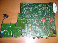
Here's how the relay is currently wired.
Here's how the relay is currently wired.
An externally hosted image should be here but it was not working when we last tested it.
In practice, how would can that be done? If say I wired in some RCA sockets would the wires from the RCA outputs go into each respects NC contacts? Where would the input wires from the op-amps go?Make sure the normally closed (NC) contacts are wired between the outputs and GND
Can anyone explain to me the scientific reasons why separate transformers for each chip makes such a big improvement? There are voltage regulators and PSU caps between the transformer and the chips; are these incapable of providing low noise, stable voltage/current?
Is there some additional noise/instability/interactions between the multiple voltage out connections from one transformer that you can avoid by using separate transformers?
Is there some additional noise/instability/interactions between the multiple voltage out connections from one transformer that you can avoid by using separate transformers?
I have a 50VA TX on its way. For installation in a CD67, do I just wire it in place of the stock TX at U308, U309 & U310? I have a super reg for supplying +5V to the servo IC's so i presume I don't need to install separate regs for each chip like others have done in the CD63?
Also if I am not using any of the analogue part of the CD67 circuit (other than the DAC) can I just remove my +/-12V regs?
I have a spare 5V super reg left over from my CD6000KI so I was going to use that for the analogue DAC supply under the PCB as per Ray's 57 pdf.
Also if I am not using any of the analogue part of the CD67 circuit (other than the DAC) can I just remove my +/-12V regs?
I have a spare 5V super reg left over from my CD6000KI so I was going to use that for the analogue DAC supply under the PCB as per Ray's 57 pdf.
Can anyone explain to me the scientific reasons why separate transformers for each chip makes such a big improvement? There are voltage regulators and PSU caps between the transformer and the chips; are these incapable of providing low noise, stable voltage/current?
Is there some additional noise/instability/interactions between the multiple voltage out connections from one transformer that you can avoid by using separate transformers?
I'm a bit dubious about it myself TBH, although it can be easier to fit several small ones than one big one. Running all regs from one transformer means they're all running off the same PSU reservoir cap. The DAC (digital in particular) depletes that quite quickly. Even a 22,000uF cap is discharged quickly when providing all 5v supplies. I interpret that as more work for the 5v regs to smooth. Perhaps 1 transformer and 1 large smoother is just as good, but again, several small reservoir caps can be easier to fit than one big one. I already have two large toroids for output and servo, and no room for a third, so really it's a combination of peace of mind and practicality of space for me.
I have a 50VA TX on its way. For installation in a CD67, do I just wire it in place of the stock TX at U308, U309 & U310? I have a super reg for supplying +5V to the servo IC's so i presume I don't need to install separate regs for each chip like others have done in the CD63?
Also if I am not using any of the analogue part of the CD67 circuit (other than the DAC) can I just remove my +/-12V regs?
Yes to both. You can remove the 12v regs and smoothing caps.
Cheers,
Ben
Yes to both. You can remove the 12v regs and smoothing caps.
Cheers,
Ben
Ah yes, the reservoir caps. I can get behind the idea of one for each chip where space is a constraint.
My thinking was that there's a reg and a cap between each chip and the transformer so as long as the cap can handle the current spikes and the reg can maintain the correct voltage...the chip doesn't "know" how many other chips are being supplied by the transformer.
If the stock Tx is incapable of meeting the electrical demands of the different chips then it makes sense that a higher wattage tx is required (or two smaller txs to fit in the case).
In the cd63 I can see why additional regs will make a difference because those voltages are unregulated as stock. But having 3 or more TXs may not be responsible for the sonic improvements. It's hard to believe the power requirements of a CD player exceed 100 watts!
Regarding my obsolete regs; perhaps I could install 5V regs in their place and use them and their reservoir caps to power other chips?
You probably don't want to put 5v regs there. When it comes to regulating the chip supplies, you want to put the output of the regulator and the local decoupling cap as close as possible to the load.
Good advice once again. Thanks Ben!
Looked in to output transformers yet? I forgot to mention Jensen USA as a more local option for you.
Looked in to output transformers yet? I forgot to mention Jensen USA as a more local option for you.
Maybe if I ever do a second player. I don't think I could do that to my poor DOS. I haven't even given him the regulation he deserves yet.
Yup they look nice!
Have you done "the coax mod" on your player? Think its worth doing on the 67 too?
Its taking the digital signals straight from the servo PCB to the decoder via grounded coax, right? Then again from decoder to DAC?
Have you done "the coax mod" on your player? Think its worth doing on the 67 too?
Its taking the digital signals straight from the servo PCB to the decoder via grounded coax, right? Then again from decoder to DAC?
I'm looking back through the thread for when Ray first did it and also the Fidelity Audio guy.
I've got the article from Bob Noriega (February 1995!! Jesus - nearly 20 years ago!?!) describing what to do but I'm trying to find out if anyone needed to add any series caps or resistors or anything.
The mini-coax I've ordered is this stuff from Maplin:
Miniature Coax Cable (priced per metre) | Maplin
I have done this on all my mods:I haven't done that one yet. Maybe someone else can chime in.
Attachments
Last edited:
You only have shielded cable for optical out? Or others on top of the board?
I was talking about coax for HF and RF signals from the laser IC to the decoder and the data and click signals from decoder to DAC etc
I was talking about coax for HF and RF signals from the laser IC to the decoder and the data and click signals from decoder to DAC etc
In the cd63 I can see why additional regs will make a difference because those voltages are unregulated as stock. But having 3 or more TXs may not be responsible for the sonic improvements. It's hard to believe the power requirements of a CD player exceed 100 watts!
That's true, such large transformers are not needed to get good results. But a beefy supply helps to prevent noise caused by sudden load changes, that's why it works so well on the driver-chips. By using multiple transformers, all the different supplies become separated from each other. This way, high-frequency noise has no chance to travel over the supply-lines (which would otherwise be common to all circuits) and penetrate other circuits. This results in a cleaner supply-voltage and better sound!
Regards,
Ray
As Ben said though; do you not think the sudden load changes are absorbed by having enough reservoir cap capacity and good regulators rather than lots of transformers?
Just rationalising things 🙂
Think I'm going to install one additional tx but no more.
I'm still searching the thread; Ray did you coax all your digital signals in the end? Was the improvement as dramatic in your CD67 as Bob Noriega suggests in his article on CD63?
Just rationalising things 🙂
Think I'm going to install one additional tx but no more.
I'm still searching the thread; Ray did you coax all your digital signals in the end? Was the improvement as dramatic in your CD67 as Bob Noriega suggests in his article on CD63?
You only have shielded cable for optical out? Or others on top of the board?
I was talking about coax for HF and RF signals from the laser IC to the decoder and the data and click signals from decoder to DAC etc
IMHO the use of coax only benefits when the distance between input and output are far apart where noise and interferences may be pick. That is the reason I only use coax for the digital outputs as the path is quite long.
IMHO the use of coax only benefits when the distance between input and output are far apart where noise and interferences may be pick. That is the reason I only use coax for the digital outputs as the path is quite long.
Either far apart, or if the signal travels through a particularly noisy/busy part of the circuit perhaps?
When building guitar amplifiers I've found the use of coax to be critical; even runs of two inches can make a good contribution to reduction of noise.
- Home
- Source & Line
- Digital Source
- Marantz CD63 & CD67 mods list