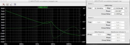
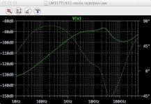
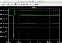
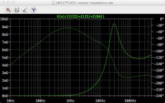
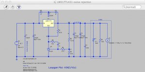
Ok I went back to the LM317+TL431 circuit and looked at all the aspects I had modelled in the other thread but this time with a target of 15V. It's a case of balancing variables to try to optimise things. I finally settled on the circuit values shown in the attachment below. I've also pasted graphs of the modelled open loop gain and phase analysis, PSRR, transient response and output impedance.
The values would seem to provide ok results to each albeit not as good as the 5V circuit. I'm sure there might be a smarter/easier way to optimises the factors affecting the feedback loop - if someone can improve on this I would like to hear it. The genesis of the discussion in the other thread was Fig. 23 from the TL431 datasheet and the question "what happens if we shift the resistor to the output of the LM317?"
I've also included a zip file of everything that's needed to do this analysis.
I hope this helps.
https://dl.dropboxusercontent.com/u/70685392/Electronics/LM317TL431%20latest/LM317TL431%2015%20volt.zip
Attachments
Last edited:
One thing I would like to learn how to do in Eagle is to easily get a trace to "hug" an existing one (with the appropriate separation wall of no copper) so that there are no small islands or channels between the traces...
Here are the latest versions:
Eagle files ZIP
Can you share the .brd and .sch files from Eagle? It may save me some time on my other project.
One thing I would like to learn how to do in Eagle is to easily get a trace to "hug" an existing one (with the appropriate separation wall of no copper) so that there are no small islands or channels between the traces...
Use the "Polygon" command and disable "Orphan"
Google "Eagle Orphan" and you'll find a lot of examples
Cheers ,
Rens
I just purchased some boards (2/2OZ, FR4,1.6mm), let's hope it works. And if/when it works I can sell you guys some boards for really good price, if interested... But let's wait until I get the boards, build it and test it.
Good luck! 
Who did you use for the boards? (Someone like Seedstudio Fusion Premium?)
Thanks for the files above!
Who did you use for the boards? (Someone like Seedstudio Fusion Premium?)
Thanks for the files above!
While waiting for the boards, this is a rough idea how the amplifier will be built (with ucd700oem).
An externally hosted image should be here but it was not working when we last tested it.
While waiting for the boards, this is a rough idea how the amplifier will be built (with ucd700oem).
An externally hosted image should be here but it was not working when we last tested it.
Wow , looks great !
What software did you use for the 3D ?
Cheers ,
Rens
What software did you use for the 3D ?
I used Google Sketchup. Additionally, I used EagleUp-plugin (Eagle export + Sketchup import) to transform the PSU board into 3D model.
Very cool.
I have hit a roadblock in my other project. I didn't realise the Light and Hobbyist versions of Eagle are so constrained regarding board size and Eagle Pro is expensive!
I have hit a roadblock in my other project. I didn't realise the Light and Hobbyist versions of Eagle are so constrained regarding board size and Eagle Pro is expensive!
Which IRF540 are you planning to use? There seems to be a few on Mouser at quite varying prices. irf540 MOSFET | Mouser Do they need heatsinking?
Rens, given the topic is rather similar, I would appreciate any input you can provide on my project here http://www.diyaudio.com/forums/power-supplies/258769-enough-current-turn-3-mosfets.html#post3982623
Piisami, roughly how long before you get your boards?
Piisami, roughly how long before you get your boards?
Last edited:
Which IRF540 are you planning to use? There seems to be a few on Mouser at quite varying prices. irf540 MOSFET | Mouser Do they need heatsinking?
Originally I was planning to use IRFB4115PBF
Then, doctordata suggested a better alternative FDP083N15A. I think I will use that. I haven't ordered those yet but will do that soon.
Heatsink should not be needed.. At least it should be adequate heatsinking by just to bolting it to the chassis..
Piisami, roughly how long before you get your boards
The boards are already on the way, I should get them within a week.
Just pointed to this thread, while I think the central topic over I have an incidental question.
That is a very adventurous Loop Gain number.
You must have either conditional stability, pushed up the UnityLGFrequency a lot, or both.
What does the LG plot look like?
How have you implemented this?
Best wishes
David
...I've multiple amp channels... with 83dB loop gain at 20kHz...
That is a very adventurous Loop Gain number.
You must have either conditional stability, pushed up the UnityLGFrequency a lot, or both.
What does the LG plot look like?
How have you implemented this?
Best wishes
David
Last edited:
Good news and Bad news
Hi Sami ,
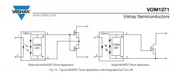
Bad news first , I'm afraid the output pins on the VOM are reversed as I read in another thread , Not 100% sure , but check it out . Vishay's drawing of the chip is a little confusing to me .
No big deal , happens to the best , open up any TV , Amp or whatever piece of equipment and a good change to find some patch wires 🙁
Good news , painters finished today , so start programming and testing the chips tomorrow .
Keep you informed
Cheers ,
Rens
The boards are already on the way, I should get them within a week.
Hi Sami ,
Bad news first , I'm afraid the output pins on the VOM are reversed as I read in another thread , Not 100% sure , but check it out . Vishay's drawing of the chip is a little confusing to me .
No big deal , happens to the best , open up any TV , Amp or whatever piece of equipment and a good change to find some patch wires 🙁
Good news , painters finished today , so start programming and testing the chips tomorrow .
Keep you informed
Cheers ,
Rens
Attachments
Last edited:
I'm afraid the output pins on the VOM are reversed as I read in another thread , Not 100% sure , but check it out .
😱 I triple checked it and you are absolutely right, I have to figure out something..

😱 I triple checked it and you are absolutely right, I have to figure out something..
I'm will make a pin swap adapter as first aid

The adapter will use a piece of prototype board and 4 pins. VOM is rotated 90 degrees and the pins are connected to the psu board and jump wired to the correct pins of VOM. I'll draw a sketch later..
- Status
- Not open for further replies.
- Home
- Amplifiers
- Class D
- Hypex Linear PSU DC-error protection