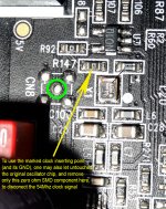
A revision (correction) of my previous post, for the insertion point of DACs clock signal (when using a external clock device/board).
Attachments
Last edited:
Coris,
what is your feeling about TCXO and better OCXO ?
Do you believe that your Clock with divider should be better for a lower price ?
If you intend to ask about comparing OCXO with TCXO, there is clear in my opinion that OCXO is a better device. But the price of an OCXO is also very high comparing to a TXCO. When I say is better I refer to the frequency stability. But when about to use such devices for audio purposes, then are many other parameters we may consider to appreciate one or another.
Personally, I do not want to pay the price for a OCXO to use it in audio systems. This is not necessary/justified at all. One can get very good results with a quite common oscillator with good jitter/phase noise figures, and a 10-50 ppm frequency stability. NDK oscillator it may be an example, the Crystek devices or SAW another one, and so on...
And yes, I appreciate that the noises induced by the power systems are more important factors to disturb a clock signal, than the temperature for the frequency stability over long time periods.
The patterns of the noises induced by actual regulators and power sources, as of the mechanical vibrations the clock oscillators are exposed to, when disturbing a clock signal, are very different and quite particular, than a temperature variation and even a power source variation over long time periods, for that osculating device. In my opinion there is comparable a slow temperature variation over the frequency stability, as the slow tension variation at the Vcc pin of the oscillator device.
As the temperature variation do, the discharging rate variations of a battery powering an oscillator, have the same very low impact (or no any impact) for the clock signal and the audio system outputted signals. While a quite noisy regulator powering a clock oscillator, or a vibrating environment for the clock chip is quite easy to hear it how is disturbing the quality of outputted audio signal...
Last edited:
To avoid some confusions for the new members here, about the clock mod in 105/105D models, I think to publish again this picture with the DAC oscillator details.
Thanks for the explaination.
2 quick questions
Does anyone happen to know the rating of the main fuse on the usa smps... I know it would be a 120v for here in the us but what is the current rating?
Second. . Would increasing the feedback resistors from 1.72kohm to 1.8 kohm..at the iv and buffer opamps be a problem?
TIA
... . sent from an oasis in the wilderness. ... ..
For those interested, I have made a tutorial about how to solder/unsolder oscillator chips in a way to make it easier to experiment with. A more DIY friendly method...
Here is the link:
http://www.diyaudio.com/forums/pc-based/197116-xonar-st-stx-mods-60.html
Here is the link:
http://www.diyaudio.com/forums/pc-based/197116-xonar-st-stx-mods-60.html
2 quick questions
Does anyone happen to know the rating of the main fuse on the usa smps... I know it would be a 120v for here in the us but what is the current rating?
Second. . Would increasing the feedback resistors from 1.72kohm to 1.8 kohm..at the iv and buffer opamps be a problem?
TIA
... . sent from an oasis in the wilderness. ... ..
My answer (first question) is: it will be no problem to vary the feedback resistor value in reasonable limits. I mean no harm, but of course it may be problems for the outputted sound quality... So, just experiment with... I have a thought that the resistors values are calculated in respect with the existing circuit fair functionality. So changing the values for the components it may alter the circuit parameters. But for sure in your case a change from 1,72K to 1,8K it may not be any problem at all.
Else, I never bothered to know the value of the SMPS fuse... So, you may read it by yourself, to get best informations...
I just had not yet opened that side of the Oppo to see the fuse so I was trying to save some trouble...
No worries...
cheers Coris
No worries...
cheers Coris
I personally have not a good answer to that question. Maybe some one else know the fuse value, and it will want to share the "secret"...
But I think the fastest way for you to find out is just to uncover the player`s SMPS. There are only few screws to be unscrewed, and the cover very easy to be removed...🙂
BTW, may you then want to publish its value?😀
But I think the fastest way for you to find out is just to uncover the player`s SMPS. There are only few screws to be unscrewed, and the cover very easy to be removed...🙂
BTW, may you then want to publish its value?😀
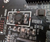
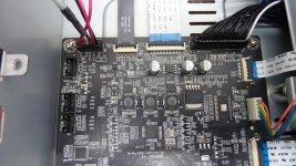
Hello Everybody, I hear from Coris, than the 105D model is not really common here.
So I post some pictures of the motherboard and particularly the clock on it. (27Mhz for HDMI)
For the CPU, same as 105/103, under the heatsink
Also a picture on the DC/DC converter, quite different as the MB of 103/105
Wish it can useful. 😀
So I post some pictures of the motherboard and particularly the clock on it. (27Mhz for HDMI)
For the CPU, same as 105/103, under the heatsink
Also a picture on the DC/DC converter, quite different as the MB of 103/105
Wish it can useful. 😀
Attachments
Thanks Asterix007 for your pictures.
BTW, I personally appreciate that we can very well use this thread for the last 105D Oppo model and upcoming ones, and not spread the discussions over threads dedicated to each specific model in this same family.
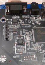
So, we can conclude now (about the 105D clock system) that are:
- one 27Mhz clock for HDMI/DARBEE chip,
- one 27Mhz clock for the main processor,
- one 54Mhz clock for DACs.
I`m glad for this choice of the designers, because this clock configuration it fit very well, and it simplify even more the implementation of my clock divider solution.
My comments so far, after I have seen these pictures:
I just do not understand what the Oppo designers had in their minds, but using two different oscillators chips with the same frequency is quite strange (to use a more elegant word...).
Why not take a trace from the processor oscillator, to feed with the same frequency clock the HDMI chip not so far away? I can not see any problems to have a clock trace inside the PCB, or place the processor oscillator somewhere in between the chips which need this clock. Or any of many other reasonable solution to avoid using two oscillator chips with the same frequency...
It can be an explanation for the reasons it were used different clock chips here, if these chips are resonators, but not oscillators. But a decision to use two resonators with the same frequency instead of only one oscillator chip for both targeted devices, it is however a bad decision (taken maybe by some financial "specialists"...).
I can see in a picture a very well defined switching power supply circuit area. The designers have thought (very right this time) to shield this very noisy kind of circuit, planted right in between some sensitive devices, and very near to the HDMI oscillator.
It were designed all what is needed to place a shield cover over this PSU. Then this idea it were abandoned, for sure for a "lower production price" reason... I feel the need to use a non elegant word here, but I will not do it right now...
So, my first recommendation to the modders out there, is to find a way to cover/shield this PSU on this motherboard pictured here, before proceed to an improvement of the oscillator/clock right beside this noisy small SMPS.
In my opinion, injecting a clock signal through a coax connection to clock the HDMI chip it will minimise quite much the impact of noisy circuit beside in this area. However it is a very good idea to have this small SMPS shielded, as the silk printed on the PCB shows, and Oppo financial specialists decided not to do it...
BTW, I personally appreciate that we can very well use this thread for the last 105D Oppo model and upcoming ones, and not spread the discussions over threads dedicated to each specific model in this same family.
So, we can conclude now (about the 105D clock system) that are:
- one 27Mhz clock for HDMI/DARBEE chip,
- one 27Mhz clock for the main processor,
- one 54Mhz clock for DACs.
I`m glad for this choice of the designers, because this clock configuration it fit very well, and it simplify even more the implementation of my clock divider solution.
My comments so far, after I have seen these pictures:
I just do not understand what the Oppo designers had in their minds, but using two different oscillators chips with the same frequency is quite strange (to use a more elegant word...).
Why not take a trace from the processor oscillator, to feed with the same frequency clock the HDMI chip not so far away? I can not see any problems to have a clock trace inside the PCB, or place the processor oscillator somewhere in between the chips which need this clock. Or any of many other reasonable solution to avoid using two oscillator chips with the same frequency...
It can be an explanation for the reasons it were used different clock chips here, if these chips are resonators, but not oscillators. But a decision to use two resonators with the same frequency instead of only one oscillator chip for both targeted devices, it is however a bad decision (taken maybe by some financial "specialists"...).
I can see in a picture a very well defined switching power supply circuit area. The designers have thought (very right this time) to shield this very noisy kind of circuit, planted right in between some sensitive devices, and very near to the HDMI oscillator.
It were designed all what is needed to place a shield cover over this PSU. Then this idea it were abandoned, for sure for a "lower production price" reason... I feel the need to use a non elegant word here, but I will not do it right now...
So, my first recommendation to the modders out there, is to find a way to cover/shield this PSU on this motherboard pictured here, before proceed to an improvement of the oscillator/clock right beside this noisy small SMPS.
In my opinion, injecting a clock signal through a coax connection to clock the HDMI chip it will minimise quite much the impact of noisy circuit beside in this area. However it is a very good idea to have this small SMPS shielded, as the silk printed on the PCB shows, and Oppo financial specialists decided not to do it...
Last edited:
Coris, what type of coax do you choose to transmit the clock signal ?
Concerning cover shield ! Well done ! I check to find a solution...
Concerning cover shield ! Well done ! I check to find a solution...
Last edited:
I will want to chose a smaller diameter coax anyway... I think 2mm thick coax is quite much, and is enough rigid to be used in tight places...
The 0,8 mm one I have now it do for me a very good job (it will be provided with my kit), is very flexible, but a little bit difficult when to fit it into connectors. Just for solder it in place is all right.
Else one may well use a more easy to handle 1-1,5 mm type coax.
For shielding that SMPS unit, I will suggest at least some steel based material/thin plate, or much better, some special made EMI shielding material. Take out the marked (silk) dimensions, design it on a paper that box, cut it and bend it accordingly, then find the right metal material and copy the paper model on it. Solder it in place. Done it! Watch for the results on your display...
Last edited:
I bought it for a year ago from China, but I have lost the informations. You may use Google, as I will do next time I will buy again...
However enough difficult to find in small quantities. But is more easy to find in few teens of cm, already finished with connectors on it. Then you may remove the connectors and use the cable as you need.
However enough difficult to find in small quantities. But is more easy to find in few teens of cm, already finished with connectors on it. Then you may remove the connectors and use the cable as you need.
Hi Coris,
Sorry, but I can not find any electric diagram of OPPO 105 audio part, apart from some photos. Do You have or any of participants such diagram. It could be very helpfull with any mods.
Sorry, but I can not find any electric diagram of OPPO 105 audio part, apart from some photos. Do You have or any of participants such diagram. It could be very helpfull with any mods.
There are no any schematics published about this player. This is quite normal as Oppo may not want to share details about his products... If by chance someone it may have such, as a result of his own researches, then it may not be very willing to share it... Understandable from my part...
All we can have so far are pictures... and some knowledge/findings about how the things works. Some parts of knowledges and findings are shared here in this thread.
All we can have so far are pictures... and some knowledge/findings about how the things works. Some parts of knowledges and findings are shared here in this thread.
Last edited:
Update
Two updates on my mods
1. Decoupling the DAC ps rails with Murata SMD Caps.(See post #646)
With respect to Joe's recommended use of the Murata 10uF/25V SMD caps
to decouple the power supply rails of the DAC, I suggest that it is best to remove the original 220uf Tk electrolytics from this position and use only the Muratas.
They make for a faster and more open presentation of the soundstage.
They even bettered using 270uf oscons in combination with the Muratas
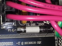
2. The main PS fuse is a 250v 5A fuse.
I will try upgrading to an audio grade fuse... I have had good luck with this in my preamp.
Any recommendations for a fuse holder in this position?
Two updates on my mods
1. Decoupling the DAC ps rails with Murata SMD Caps.(See post #646)
With respect to Joe's recommended use of the Murata 10uF/25V SMD caps
to decouple the power supply rails of the DAC, I suggest that it is best to remove the original 220uf Tk electrolytics from this position and use only the Muratas.
They make for a faster and more open presentation of the soundstage.
They even bettered using 270uf oscons in combination with the Muratas
2. The main PS fuse is a 250v 5A fuse.
I will try upgrading to an audio grade fuse... I have had good luck with this in my preamp.
Any recommendations for a fuse holder in this position?
Attachments
Do you use many of 10µ caps in parallel to get at least 200µ or more, or you use just 10µ?
I really doubt if one can have good results with only 10µ decoupling...
If you let in place the 220µ, and add 10µ, then it can mean something, but else... However, there it should be a quite large capacity.
I have a comment about this (legendary) fuse (replacing with "audio grade").
I guess in your preamp it is about another type PSU (linear). In such case the construction of a fuse placed on a DC line it may have impact for the noises levels in the system.
When about this player, here we have a SMPS protected in its very first input stage by this fuse. This SMPS is a switching device, very noisy right before its the last filtering caps. The impact of this fuse, placed on an AC isolated circuit, for the noisy device it protect is pure and simple, nothing. If this fuse it should be placed on the DC lines, then we may want to think at a "audio grade" one. But in this case is really not to think about.
In my opinion, you may direct your efforts and investments in other directions, but not thinking at all at this fuse.
Last edited:
- Home
- Source & Line
- Digital Source
- Oppo's BDP105 - discussions, upgrading, mods...