...
Are the sSi590 better than CCHD957 ?
Regards
CCHD957 is better
Hi All,
Hope one of you can help with this ... I've been fortunate enough to buy a pair of XO & isolator boards (AKX02 & AKL-AKM-S02), however, understood from the seller that there was a routing missing on the AKL-AKM-SO2 in terms of leading the XO's clock back to the Amanero board (for Amanero slave use). In case this is mentioned in this thread might one of you lead me to the post where a solution is described - or maybe just briefly describe it again?
Thanks for any help you may give ;-)
Cheers,
Jesper
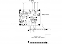
Jesper: Check here... you cut the trace between the marked IC pin and the hole with a X over. then wire to the MCK-pin instead.
Or you do as me, just jumper between both holes, and remove the pin that should go into the X-marked hole instead.
Or you do as me, just jumper between both holes, and remove the pin that should go into the X-marked hole instead.
An externally hosted image should be here but it was not working when we last tested it.
Hi 🙂 ... thanks for your feedback and the instructive drawing. I'll look into it - and also look very much forward to (soon I hope) listening to the DAC.
Hilsner til Sverige!
Jesper
Hilsner til Sverige!
Jesper
Working, at long last. Turbo connection to BIIISE, after increasing current thru the 1.2v Trident, and correctly setting config bits on the Amanero for pins 1 & 11. Will now play everything I have thru Daphile, both DSD and PCM at native rate up to 192k, and upsampled in the software to (at least) 352k. Haven't tried 384k yet, and 352k takes a few moments to stabilize, with background static-y noise for those moments, then fine.
Curious about the BIIISE dip switches, however. If I am upsampling in software to the highest integer multiple, which is, as I said, 352k so far, then when turning off oversampling filtering and reclocking via SW2 switch 5, I get the loud, hashy noise I had previously gotten, and that noise does not dissipate or go away with time. Perhaps I'm not clear on what is going on inside the Sabre chip, but my hope had been to bypass what is going on and control filtering via software. Any thoughts? Thanks for all the help and suggestions getting to this point - Pat
Curious about the BIIISE dip switches, however. If I am upsampling in software to the highest integer multiple, which is, as I said, 352k so far, then when turning off oversampling filtering and reclocking via SW2 switch 5, I get the loud, hashy noise I had previously gotten, and that noise does not dissipate or go away with time. Perhaps I'm not clear on what is going on inside the Sabre chip, but my hope had been to bypass what is going on and control filtering via software. Any thoughts? Thanks for all the help and suggestions getting to this point - Pat
Hi Miksi,
This might not apply to your Buffalo III implementation, but I found that trying to play 352/384 via amanero/acko isolator with P-sync, I had lots of noise/glitching. I found that the VDD(1.2v) Trident couldn't supply enough current to prevent VDD voltage droop causing the noise. After modifying the trident to supply more current, I've been able to play 352/384 files without any issues.
Hope this helps.
Cornelius.
Russ suggested 20-27 ohm resistor. What value did you use and on which resistor can we measure ccs current on tridents? Now, I'm going to measure voltage when noise appears.
Measured voltage on 1.2 VDD is 1.1642V regardless of sample rate. And now noise (on 352 and 384) resembles on white + some faint modulated high frequency tone, like tuning to distant AM station and appears about 30-40 sec after stop playing music or test signal.
Hi Acko,
I have the Pi and Doede's DDDAC, and am looking to build an isolator much similar to Enrico (Emyeuoi). Please advise where could I get the board and associate parts?
Many thanks,
Chanh
I have the Pi and Doede's DDDAC, and am looking to build an isolator much similar to Enrico (Emyeuoi). Please advise where could I get the board and associate parts?
Many thanks,
Chanh
Measured voltage on 1.2 VDD is 1.1642V regardless of sample rate. And now noise (on 352 and 384) resembles on white + some faint modulated high frequency tone, like tuning to distant AM station and appears about 30-40 sec after stop playing music or test signal.
Are you able to check the 1.2v line on a scope to see what is going? Multimeter shows average only
Hi Acko,
I have the Pi and Doede's DDDAC, and am looking to build an isolator much similar to Enrico (Emyeuoi). Please advise where could I get the board and associate parts?
Many thanks,
Chanh
Please check webpages below. Look for "Digital Isolator/Reclocker". Support material has all the details of the build information
Russ suggested 20-27 ohm resistor. What value did you use and on which resistor can we measure ccs current on tridents? Now, I'm going to measure voltage when noise appears.
Miksi -
I went with 30 ohms, based on the calculations posted on the TP forum, which differ somewhat from those in the Buffalo implementation guide. I believe that R4 on the stock 1.2v Trident is 10 ohms. I'm sorry, but I don't know where to measure the actual ccs current, I just crossed my fingers and hoped for the best.😉 - Pat
On Tridents, you can measure the voltage across R7 (1R). mV = mA.
BBB-S03
For those who wish to test S03 with BBB an update to the drivers can be found here -> http://bbb.ieero.com
Many thanks to Miero for his efforts!
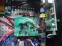
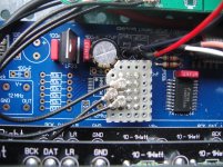
Suitable setup as shown in the annex:
For those who have BBB - connection as shown for full synchronous clocking. No cape necessary.
On-board clock of the BBB should be disabled (or removed) and use appropriately divided clock from S03 instead.
Currently BBB has single 24.576MHz clock support only so only one S03 XO (49.152MHz or 98.304MHz) needs to be mounted or enabled. If 98.304MHz used then you get 'Turbo' Sync capability to 9018 DACs. Of course other DACs like PCM1794 also possible with BCK out from S03 as MCK'
Sample frequencies are limited to 48K, 96K and 192K as result of this single clock of the BBB. If future versions allow dual audio clocks then full range of sample frequencies will be possible and then CKSEL can be used to automatically switch.
Until then upsampling 44.1k-based audio files using software utility is a suitable option
For those who wish to test S03 with BBB an update to the drivers can be found here -> http://bbb.ieero.com
Many thanks to Miero for his efforts!
Suitable setup as shown in the annex:
Attachments
Hi Acko,
The S03 is working nicely since last Sunday 🙂
As we remain few weeks ago, I re-ordered the XO and I re-check the circuit. I found that the pin 3 of the U5 give me 4,6V that, if you remember, was the voltage that I read in the broken XO during the troubleshooting. I substitute the U5 and the pin 3 give me 0,2V (without XO installed).
Should be nice to understand if the U5 was damaged by the XO or viceversa.
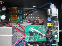
As you suggest I check the XO before to install them in the PCB and at the out pin give 1,62V as expected. I install it in the PCB, connected between the rpi and the DAC and is working perfectly 🙂
I am really really happy with the S03 🙂 The DDDAC make another HUGE step ahead with your S03 isolator/reclock.
Thank you Acko for your kind work and support!!
Best Regards,
Enrico
The S03 is working nicely since last Sunday 🙂
As we remain few weeks ago, I re-ordered the XO and I re-check the circuit. I found that the pin 3 of the U5 give me 4,6V that, if you remember, was the voltage that I read in the broken XO during the troubleshooting. I substitute the U5 and the pin 3 give me 0,2V (without XO installed).
Should be nice to understand if the U5 was damaged by the XO or viceversa.
As you suggest I check the XO before to install them in the PCB and at the out pin give 1,62V as expected. I install it in the PCB, connected between the rpi and the DAC and is working perfectly 🙂
I am really really happy with the S03 🙂 The DDDAC make another HUGE step ahead with your S03 isolator/reclock.
Thank you Acko for your kind work and support!!
Best Regards,
Enrico
Thanks Enrico, great to see your progress!
I am still not sure how the earlier U5/XO damage occurred, possible transients somewhere during tests or component issues. Will keep this in mind if further problems are reported
I am still not sure how the earlier U5/XO damage occurred, possible transients somewhere during tests or component issues. Will keep this in mind if further problems are reported
Hi Acko,
I just re-read my post... the damaged one was the U3. The U5 is not installed at all.
Sorry for the confusion 😱
Regards,
Enrico
I just re-read my post... the damaged one was the U3. The U5 is not installed at all.
Sorry for the confusion 😱
Regards,
Enrico
Hi Acko,
I just re-read my post... the damaged one was the U3. The U5 is not installed at all.
Sorry for the confusion 😱
Regards,
Enrico
OK, thanks, U3 it is then
- Home
- Group Buys
- Amanero Isolator/Reclocker GB