I don't know if it's important but could it perhaps be that the servo wont work correctly if the output stage isn't actually in place?
That's definitely the case.
DC servo will not work unless it is connected to the output - it senses the output, compares it with "zero" and generates the corrective signal until it's actually zero.
For most of VFA designs, you can just connect PD+, ND- and NFB pins together - the circuit will balance itself.
However, in most of CFAs, NFB will produce too much load for front-end output, so distortion and some other parameters will look worth than they would look with "real" power section attached.
And yes, servo will fight all the time 🙂 Just give it the right point where you want to have "zero" - servo will set it for you.
Cheers,
Valery
Terry you must connect INP OUT together.
Use the right method for 'first fire test",RESISTORS instead of fuses.
Possibly you haven't any problem.
Good luck🙂
Use the right method for 'first fire test",RESISTORS instead of fuses.
Possibly you haven't any problem.
Good luck🙂
Hi Guys,
You gave me hope, but alas, not the problem. I connected up the OPS and started it up through my lightbulb tester. With the servo in place It started cold and about -100mv offset. As soon as it started warming up it started moving + offset. I tried adjusting but it would slow the rise but only for a moment and then continue rising positive. When I shut it off it was at +600mV offset. Then I pulled the servo and reset everything and it holds fairly close to zero but slowly fluctuates between -4mV to +7mv offset.
Another thing I notice is that Q3,4,7&8 get pretty hot. Not too hot to touch and hold but hotter than I'm used to seeing.
You gave me hope, but alas, not the problem. I connected up the OPS and started it up through my lightbulb tester. With the servo in place It started cold and about -100mv offset. As soon as it started warming up it started moving + offset. I tried adjusting but it would slow the rise but only for a moment and then continue rising positive. When I shut it off it was at +600mV offset. Then I pulled the servo and reset everything and it holds fairly close to zero but slowly fluctuates between -4mV to +7mv offset.
How do I give it that point? Seems it is fighting to take it somewhere else.And yes, servo will fight all the time Just give it the right point where you want to have "zero" - servo will set it for you.
Another thing I notice is that Q3,4,7&8 get pretty hot. Not too hot to touch and hold but hotter than I'm used to seeing.
Last edited:
Hi Guys,
You gave me hope, but alas, not the problem. I connected up the OPS and started it up through my lightbulb tester. With the servo in place It started cold and about -100mv offset. As soon as it started warming up it started moving + offset. I tried adjusting but it would slow the rise but only for a moment and then continue rising positive. When I shut it off it was at +600mV offset. Then I pulled the servo and reset everything and it holds fairly close to zero but slowly fluctuates between -4mV to +7mv offset.
How do I give it that point? Seems it is fighting to take it somewhere else.
Another think I notice is that Q3,4,7&8 get pretty hot. Not too hot to touch and hold but hotter than I'm used to seeing.
Something is wrong with servo. I would check if it gets the correct +/- 12V supply first.
NFB pin is connected to the power section's output, right?
Hi Guys,
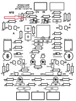
I found the issue. The screen print shows a jumper below R32. That jumper puts R32 and R34 in parallel. I hadn't noticed until I just went through the whole board again and R34 measured 15K instead of the 680k that is there. I cut the jumper and now all is well. 100K square waves are a bit rounded but up to 20k they look pretty good. Not as crisp as the CFA's though. Going to go play some music through it and see how it sounds.
Thanks for the help!
Blessings, Terry
Attachments
Last edited:
Going to go play some music through it and see how it sounds.
Blessings, Terry
Why bother, it sounds just the same as the others. 😀
Just wanted to make sure it sounds as good, which of course it does. 😀
Lazy Cat, take a picture of your A/B setup. I'd like to see how you are doing it that you can tell the difference between two super low distortion amps such as these. I would bet that you are not doing instant switching between them. I have had several people come to listen to mine and they are all at a loss to decide between amps.
BTW, I was able to find the source of the rounded 100kHz square waves. When populating the second board, I was out of 22p MICA for Cdom1 & 2, so I put ceramic there. When I tested the board with the MICAs, the square waves looked great. I had some 33p so I swapped out the ceramics and now that board looks good too. I will order some more 22p.
Blessings, Terry
Last edited:
yes, Terry go ahead and test.....and tell us what you find....😉
has anyone here made a correlation between simulations and actual testing on built amps?
what was the result? how close was the simulation to the real thing?
has anyone here made a correlation between simulations and actual testing on built amps?
what was the result? how close was the simulation to the real thing?
Hi Guys,
This seems to be an interesting amp project, I like the option to build multiple IPS with one OPS.
And lots of you are doing good work on this.
Do you think that I could build this as a newbie?🙂
Let me elaborate, soldering won't be an issue, measuring basic stuff with DMM neither.
Choosing the correct values parts might be a bit trickier since there is still some testing going on, and people suggesting other values. Intial startup will be tricky.
So besides a DMM, will an oscilloscope be necessary to get this working optimally? Minimum BW .. 200mhz? Or can build without.. and hope that additional troubleshooting is not needed? Would using a pc sound card as signal generator be sufficient in that case? Anyway, Even second hand not so cheap toys, so I'd rather know the necessity🙂
Btw, does anyone know what the power dissipation is in the output pairs? How much of the power is dissipated as heat?
If we know the % of the input power that goes to heat we can calculate the heatsink needed for that input power.
Not sure if the efficiency will remain the same or not with less or more input power.
OS: I wonder if it's possible to simulate this?
If we know the dissipation we can check the datasheet what the max junction temperature would be for this ammount of power dissipation, depending on the used transistor.
Thermal resistances can be quite easily found in datasheets.So we can then calculate what heatsink is needed, or how much input power a certain heatsink can take.
I haven't seen any calculations, are you all guessing?🙂
If I'm not mistaken, more output transistors = lower Rth
thermal resistance (for junction to case & thermal (insulation) pad) can be divide by the number of output trannies, same for the total power dissipation. The heatsink still needs to be able to get rid of the full power ofcourse.
More transistors would mean that we can survive higher junction temperature as well.
I think it might be cheaper to add more output pairs then upgrade the heatsink.. and certainly take less place🙂
I'm considering to start with 2 channels, but if all would go right I might consider 6 channels, as an (awesome) surround amp.. splitting the same power over 6 channels.. But then heatsink size does play a role ofcourse. Although that is far from sure, I'd rather take it into account already.
Keep up the good work guys🙂
This is not a tough build. If you get the boards from Jason, they are really well made with good silk screen. He is also very good and explaining things so he can certainly help you with questions you may have. If this is your first project, You might want to start with Jason's VSSA. Less of an investment and a good warm up to this amp. Not to mention it is a very good sounding amp.
Blessings, Terry
Blessings, Terry
has anyone here made a correlation between simulations and actual testing on built amps?
what was the result? how close was the simulation to the real thing?
Generally speaking, with good models, BJT based amplifiers are very close in simulation to real world results. With JFETs and MOSFETs, simulated results are more distant from reality. This said I mean we avoid mistakes of the beginners and we speak about correlation of sims and real world on properly built amplifiers.
As it depends a lot on several variables (layout, models accuracies, components qualities etc...) what kind of answer did you expect ?how close was the simulation to the real thing?
yes, Terry go ahead and test.....and tell us what you find....😉
has anyone here made a correlation between simulations and actual testing on built amps?
what was the result? how close was the simulation to the real thing?
My amplifier work from simulation without modification. I burn zobel resistor when I trying give 33 kHz square wave input. The output is really good on scope. I do not have good sound card to measure THD. The simulation result are:
PM 66 GM 8
71W/8Ohm, 1kHz -> 0.000318%
142W/4Ohm, 1kHz -> 0.000323%
Slew rate 90
PSRR 100Hz -> 118
I use topology like Honey Badger.
Thank you for Dadod (Damir), Ostripper, and Bonsai who share their knowledge to me. Thank you for Keantoken and Bob Cordell for the transistor model for simulation.
As it depends a lot on several variables (layout, models accuracies, components qualities etc...) what kind of answer did you expect ?
i wanted to know if the actual result is equal, better or lesser than simulations show, if different by how much say in percentage, no need to be too precise...
Generally speaking, with good models, BJT based amplifiers are very close in simulation to real world results. With JFETs and MOSFETs, simulated results are more distant from reality. This said I mean we avoid mistakes of the beginners and we speak about correlation of sims and real world on properly built amplifiers.
thanks for the reply....does it mean that models for jfets and mosfets are not as precise as that of bjt's?
My amplifier work from simulation without modification. I burn zobel resistor when I trying give 33 kHz square wave input. The output is really good on scope. I do not have good sound card to measure THD. The simulation result are:
PM 66 GM 8
71W/8Ohm, 1kHz -> 0.000318%
142W/4Ohm, 1kHz -> 0.000323%
Slew rate 90
PSRR 100Hz -> 118
I use topology like Honey Badger.
Thank you for Dadod (Damir), Ostripper, and Bonsai who share their knowledge to me. Thank you for Keantoken and Bob Cordell for the transistor model for simulation.
good job...

Attachments
CFA-X and "XH" (CFA , of course) - Similar to the "VSSA/peeceebee" , a very simple amp usableConfusing over all versions which working Cfa-X''H'' v1.3 and Os mod good?
with the "slew" OPS's. POST #701 -perfected (684 is an error - do NOT use ! )
Edit ... post #2739 is the official schema for the "new" version for CFA-X "H" (hawksford powered).
This second CFA-X"H" is what WE NAME MODIFIED because this was modified by BV in two versions.

- Home
- Amplifiers
- Solid State
- Slewmaster - CFA vs. VFA "Rumble"