Hello James,
I am not sure that you need to draw 1.5A to make it work properly.
Some chokes will have more mH if there is less current running.
Using it as choke input will give it a harder life. But Lundahl says it suitable for it.
HOWEVER i know you have to draw a minimum current to make it work as a choke input. The less the induction the higher current you have to sink with the bleeder. Sure the technicians here can give you the formula.
Yes better use a heatsink if you connect it to the chassis you need thick aluminium( the thicker the better) and a large surface and you will heat up all the parts mounted on the chassis.
With choke input i would use the bleeder right at the first cap. There is a lot of current flowing here so they say the connection to ground should be as short as possible. In the second choke there will just be the current flowing from the actual circuit. Will also reduce voltage drop.
Long long time ago an engineer did tell me not to use 2 identical filter stages after each other. So same induction and same cap value twice.....
i cannot explain and in some situation it might okay.
Sincere greetings, edward
p.s to many projects running now but i will surely use chokes. Have about 8 in stock. French ones, professional potted. Did use them in my Virtue sensation amp. Did '' sink '' 250ma using 2 *50 ohm 50 watts in series.Someone having the lundahls, if you pay the shipping i can send you one for free
Hi Guys,
As promised here are some pictures of my latest setup.
There is an extra RC step added to the raw power supply to lower the voltage for the 3.3v regulators and added some oscon caps. Also a small bleeder (75Ohm) is added. first C step has an extra added silmic of 2200uf/25V.
On the motherboard I now only use Oscon because it is only used for digital now.
Digital raw supply is around 8V, analog raw supply is around 11,5V.
On the underside you can see the cut traces for the digital supply. I used some pins from an IC DIL connector to be able to experiment with different caps at the DAC chip.
For now 0,068uf/65V Wima sounds better than the 0,1uf.
You might notice that the foil is removed from the caps, this is the cheapest and best mod you can do: The foil is static and influences the electromagnetic field generated around the cap by the AC currents going through.
Regards,
Attachments
-
 Photo 21-06-14 10 39 18.jpg629.9 KB · Views: 651
 -
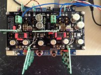 Photo 21-06-14 10 41 04.jpg645.7 KB · Views: 629
 -
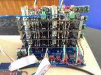 Photo 21-06-14 10 38 39.jpg714.5 KB · Views: 607
 -
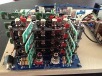 Photo 21-06-14 10 38 16.jpg656.1 KB · Views: 581
 -
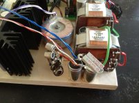 Photo 21-06-14 10 38 55.jpg522.5 KB · Views: 579
 -
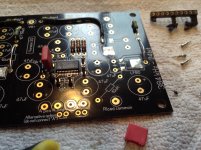 Photo 08-06-14 09 34 49.jpg501.5 KB · Views: 364
 -
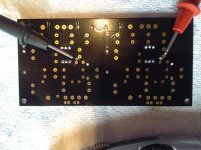 Photo 08-06-14 09 22 14.jpg466.3 KB · Views: 325
Last edited:
DDDAC - Digital Input Options: WaveIO or Raspberry Pi or something else?
Hi,
I'm strongly considering buying and assembling a DDDAC kit. The music should come from a Raspberry Pi (RPi) via Volumio or the like. Now I have two options:
1) Use some USB to I2S converter, such as the suggested XMOS WaveIO board
2) Directly use the I2S output of the RPi
However, it seems that each option has its pros and cons, so perhaps someone can enlighten me on the following points:
- The XMOS WaveIO is widely recommended for the DDDAC design. On the other hand, I heard that the board has a very high jitter:
XMOS Support Board • View topic - External clock
To me it sounds kind of weird to assemble a very low-jitter DAC and feed it with a relatively high jitter on the I2S bus. On the other hand the WaveIO-Board seems to be sounding well? And on their website Luckit | Audiophile grade DIY products they write: "[...]preserving the digital audio signals’ integrity for lowest jitter performance."
So perhaps the 2.5ns story is untrue or the XMOS jitter is handled in some specific way by the WaveIO board?
I wonder if it would not be an idea to put some I2S clock regeneration in the middle, just like the following to elminitate the jitter issue on the WaveIO-Board:
Ian’s I2S FIFO Re-clocker: Single-digit psec Jitter | H i F i D U I N O
- On the other hand the RPi is told to have approx 800ps jitter on the I2S bus, which is lower than the 2.5ns. However, the ground plane seems to have a lot of noise - probably especially when connecting the Ethernet port like I do. Maybe some isolation may help here, such as with the following module?
Isolate your Raspberry PI
or some DIY kit, which is probably cheaper:
I2S isolator
Does anyone has further information about these issues?
Hello Supersurfer,
You have a lot of courage to talk about the benefits of removing the isolation of the caps. I remember years ago i did mention a product called super black( by JVC) to cover caps where the isolation cannot be removed. A member from Belgium who also could read French like me were burned to the ground by other members.
I just did go through my French library. It was Jean Hiraga ( yes the one that also did pop up in this thread) who did mention this product in 1980 in an article about his amplifier for a moving coil cartridge. It was discussed before but dont wanna go through all my magazines. Must have an instruction about this stuff somewhere too.
You could apply it to the wimas too i guess.
If i find the instruction i could scan it and mail it to you.
Can send you an aluminum plate with holes by real mail if it fits in a sturdy envelop.
This is the replacement i did make for my sensation bottemplate in order to be able to replace parts on the circuitboard with disconnecting everything.
Now we wait for James to see how it sounds.
Sincere greetings, Edward
Attachments

Very cool Stefan 🙂
I like the idea of splitting up and running the 3.3v supply through an extra RC filter. Can I ask what values you chose for this?
Also, what is this underneath the Oscons?
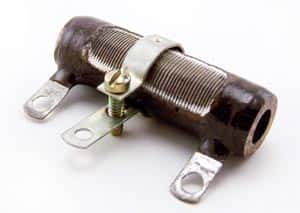
I think if I get 3 x 48ohm 50w resistors for my bleeder, then I can use all 3 in parallel to simulate the 0.75A full load for testing, then remove 1 of them when I connect it to my dac. If I understand it correctly that is...
I like the idea of splitting up and running the 3.3v supply through an extra RC filter. Can I ask what values you chose for this?
Also, what is this underneath the Oscons?
An externally hosted image should be here but it was not working when we last tested it.
I think if I get 3 x 48ohm 50w resistors for my bleeder, then I can use all 3 in parallel to simulate the 0.75A full load for testing, then remove 1 of them when I connect it to my dac. If I understand it correctly that is...
Hello James,
That is a wire wound resistor with an adjustable leg so you can change its value.
The free air power rating of the 50 watt is 20 watt so it will be okay for testing but it will turn into a fire cracker if you push it to far.
I am not sure you need to do a test with 3 resistors. I mean if you have to buy them. If you really want to be sure just use a sufficient rated one for testing ( measuring tension will take a few seconds if the meter is already connected, just switch on, it will gradually rise because the choke will slow down the charging, the caps are not big so it will be a few seconds i guess).
The big 150ohm are in parallel so that would be the bleederof 75 ohm Superman is talking about And the adjustable resistor is the one that is used to '' fine tune '' the voltage. Seeing the size of the wire it will not be many ohms in value. Put a choke there too??? Not a 1.5A rated one.
Sincere greetings, Edward
Ahh yes, I hadn't seen one of those before 🙂
My thinking with 3 x 50w 48ohm bleeder resistors was that I can run 2 normally in parallel and they will see half the current that my existing 24ohm one does (so won't get as hot), but also then it's very simple for me to add a 3rd one and simulate the load of the DAC too.
My thinking with 3 x 50w 48ohm bleeder resistors was that I can run 2 normally in parallel and they will see half the current that my existing 24ohm one does (so won't get as hot), but also then it's very simple for me to add a 3rd one and simulate the load of the DAC too.
Hello,
Using 24 ohm as a bleeder will provide enough current flow to make it work like a choke input no matter if the dac is connected or not.
Might be a good idea to give both resistors their own heatsink and mount them with some stand off about the bottom to get a chimney effect( stimulate some airflow) Especially when the surrounding temperature is higher like during a typical English heatwave and long listening sessions the heatsink will get real hot.
Really curious about your final thoughts.You might consider this kind of transformer. Once the secondary tension is to low or to high you just switch to thje next one.
I will try to find a digital copy of the publication about the advantages of the EI type versus the toriodal one. BUT is in French. ( reminds me of Anywhere they do French food? Yes France i believe. They seem to like it there)
Sincere greetings, Edward
Attachments
Hello Supersurfer,
You have a lot of courage to talk about the benefits of removing the isolation of the caps. I remember years ago i did mention a product called super black( by JVC) to cover caps where the isolation cannot be removed.
Sincere greetings, Edward
Hi Edward,
I would like to encourage people to experiment for them selves.
I know there are people who are more of the school of copying others by talking about things they have read about (but don't understand, and have not tried for themselves) and spread "their wisdom" on forums. I really do not care if such people would shoot off my ideas.
My experience on the DIY forums is that most contributers are smart enough to understand my meaning.
The effect of removing the foil is no "snake oil" story it is all scientifically explainable.
James,
The adjustable resistor is an ohmite and can be bought at Mouser I use a 25ohm version here.
The oscons are two times 560uf
Regards,
Last edited:
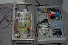
More fun this evening. I have a working solution now 🙂
Removing the first caps in the power supply, so I have choke input LCLC instead gives me a steady 13v with just the bleed resistor and 11.5v with the DAC attached. That will do nicely 🙂 Because the voltage is a little lower, I've separately joined it to the analog 8v regs as well as to the main board as I couldn't remember the headroom needed for the 8v shunts, but thought it was around 3v.
I've also added a few heatsinks I have here in the junk pile to the bleeder and mounted it external to the case. now the bleeder resistor sits at approx 68 deg C, so that's good enough for the moment till I find a better solution. I'm not going to win any prizes for neat and tidy installation, this is just a mockup for now to get it working. I'd like to swap to a 2 case setup eventually, 1 for power supply, 1 for dac ideally.
Anyway, here's some pictures
And the sound? I want to hear more 🙂 but so far, excellent separation and imaging, airy detail, but with a solid, supple character to the bass which I haven't had before with this setup. Kick drums are powerful, but tight. Accuracy is great. I found myself enjoying and analysing the instruments and the playing, rather than the sound of my equipment, which can only be good. That's the goal right?
Thanks again all for the help, especially Stefan [emoji106] 🙂
Removing the first caps in the power supply, so I have choke input LCLC instead gives me a steady 13v with just the bleed resistor and 11.5v with the DAC attached. That will do nicely 🙂 Because the voltage is a little lower, I've separately joined it to the analog 8v regs as well as to the main board as I couldn't remember the headroom needed for the 8v shunts, but thought it was around 3v.
I've also added a few heatsinks I have here in the junk pile to the bleeder and mounted it external to the case. now the bleeder resistor sits at approx 68 deg C, so that's good enough for the moment till I find a better solution. I'm not going to win any prizes for neat and tidy installation, this is just a mockup for now to get it working. I'd like to swap to a 2 case setup eventually, 1 for power supply, 1 for dac ideally.
Anyway, here's some pictures
An externally hosted image should be here but it was not working when we last tested it.
An externally hosted image should be here but it was not working when we last tested it.
An externally hosted image should be here but it was not working when we last tested it.
An externally hosted image should be here but it was not working when we last tested it.
And the sound? I want to hear more 🙂 but so far, excellent separation and imaging, airy detail, but with a solid, supple character to the bass which I haven't had before with this setup. Kick drums are powerful, but tight. Accuracy is great. I found myself enjoying and analysing the instruments and the playing, rather than the sound of my equipment, which can only be good. That's the goal right?
Thanks again all for the help, especially Stefan [emoji106] 🙂
Hello James,
Good sign that you are listening to music instead of sound.
Switching to choke input usually did give me the idea of bigger lungs for my set up. A bit like cycling after warming up and cycling after a meal with some wine.
Maybe you can just move the transformer(s) outside. I think because the currents involved are quiet high you could gain something by having some wires shorter.
ooh ooh the heatsinks. You dont have one you can attach to the side where the holes are and then mount that heatsink with a pair of stand offs to the box? A bit bigger sink, some thermal grease and a tight connection will lower the temperature. It is not to high i think but when attached to wood it is not very safe. Because of the heat the tie rap could get brittle and break and then you depend on the wooden box to care of the heat.
In the attachment you can see my present line amp. On the left the circuit with the superreg shunt from Allen Wright on the right the choke input chassis which did serve for some other projects too as you can see.
Really glad it works out fine for you and some adjustments can still me made for further improvements. loooks very promising.
Sincere greetings, Edward
Attachments
Hi James,
Very nice that you got it running! You can connect 11,5v to motherboard only, I did the same with my old setup and that works for the 8v shunts.
You will notice that the sound develops when the power supply runs in, sound will get more compact and dynamic.
You need to do something about the bleeder though, Edward is right, this is dangerous.
Much listening pleasure!
Hi Marcus,
A zener diode will introduce a lot of noise in your power supply. If you want to use a voltage reference a led is a better choice. You only need to use an array of leds for a higher voltage.
Hi Supersurfer,
thank you for pointing me to that.
The Z Diode, specialy aroud 5 -7 V has most noise. But i guss it's only some µV compared to nV of many regulators.
Regards
Marcus
Thanks guys. Like I say, please don't think this is the final solution, just all smashed together with only what I can find and salvage on a Saturday night. I'll make it nice before it gets proper use, I promise 😉
Soon it will be a comfortable, well controlled heat, even with the beautiful hot weather we always have here in England.
Soon it will be a comfortable, well controlled heat, even with the beautiful hot weather we always have here in England.
Can I just check on this, did you have all the resistors and chokes on the DAC board in the path between the power supply and the regulator? Because I still do and when I checked the voltage at the 'in' pad for the 8v regulator, I get around 10.5v with this setup.You can connect 11,5v to motherboard only, I did the same with my old setup and that works for the 8v shunts.
Do you think this is wise or should I bridge the R2/4 resistor and maybe the L1/3 choke too?
Thanks,
James
Hello James,
Just be sure to switch it off when you are not around. I did find a nice transformer 3 A and multiple secondaries. These are my chokes i could use. The one on the right has lots of induction 400 mh but serie resistance is HIGh (4.2 ohm) so not sure if it is a good candidate. The 400mH i have 3 in stock the other one some more . Did get them for a few euro. Their technical properties are close to the Lundahls but they are potted.Dont know which one will be the best. Only way to tell is buy some lundahls too and compare them.
Sincere greetings, Edward
Attachments

Can I just check on this, did you have all the resistors and chokes on the DAC board in the path between the power supply and the regulator? Because I still do and when I checked the voltage at the 'in' pad for the 8v regulator, I get around 10.5v with this setup.
Do you think this is wise or should I bridge the R2/4 resistor and maybe the L1/3 choke too?
Thanks,
James
Hi James,
I am not sure if I had the resistor bridged but I think 10,5v will do for the shunts. You can try and measure output voltage of the shunt, if this is not lower than you have now it will be ok. Otherwise you can bridge the last resistor on the dac board. The inductors can also be bridged, they have no use with the shunts.
Hello James,
Maybe you could also reduce the '' voltage reduction '' in the chokes by doubling the value for the bleeder. If i am right you will have about a volt extra. The current draw will still be enough to make it work as a true choke input.
Also could add a very little cap after the rectifier like Supersurfer did mention a few days ago.
Sincere greetings, Edward
I'm reading about choke inputs, and don't know why a bleeder resistor is needed here.
Stefan used his PSU without, with great results, will it be greater with a bleeder ?
If somebody could correct my ignorance by giving a little "suitable for noobs" explanation...
Beside that, I'm glad I chose Belleson, they all can input 35VDC, so no need of a complex PSU !
Stefan used his PSU without, with great results, will it be greater with a bleeder ?
If somebody could correct my ignorance by giving a little "suitable for noobs" explanation...
Beside that, I'm glad I chose Belleson, they all can input 35VDC, so no need of a complex PSU !
Bonsoir,
Pourque ca fonctionne comme choke input il faut qu'il y a toujours un courant minimale a travers le self sinon la tension sera trop eleve. La valeur du courant est en rapport avec la valeur de la tension et l'induction du self. Avec 100mH il faut plus de courant compare au 200mH.
L'alimentation de Stefan a des self mais apres le redresseur il y un condensateur et chez James il y a un self juste apres le redresseur.
Sincere greetings, Edward
Hello,
To make it work as a choke inpt you need a minimum current going through the choke. If not the tension will rise to high. The value of the current, the dc voltage and the induction are related to each other. With 100mH you need more current compared to a 200mH.
Stefan did use a cap after the recifier and James first element after the rectifier is a choke.
Sincere greetings, Edward
Last edited:
- Home
- Source & Line
- Digital Line Level
- A NOS 192/24 DAC with the PCM1794 (and WaveIO USB input)