Show that in the diagram.
Then YOU can see the two wire input cable and the TWO wire output cable to each driver.
Remember to twist every two wire connecting cable.
Remember to minimise the loop at the end of every two wire connection, the beginning end and the finishing end of EVERY two wire connection.
You do this to minimise the receiving abilities of the speaker cables, which are acting as aerials. The speaker cables are connected to the -IN pin of your amplifier and interference picked up by your speaker is injected back into the amplifier with very little attenuation.
thankyou!
I will do! been looking at heaps of possible replacement speakers today, all costing more then what the vifas are! I envy you and steve for your access to cheap decent hifi parts and components!
Have you ever heard jpw's Andrew?
I will do! been looking at heaps of possible replacement speakers today, all costing more then what the vifas are! I envy you and steve for your access to cheap decent hifi parts and components!
Have you ever heard jpw's Andrew?
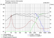
The SEAS CA22RNY is going to be a much better driver than the Vifa M21 IMO. Cast chassis for one thing. The SEAS is a reflex driver at heart, of course. I was hoping to give you an idea what to look for in frequency response.
The Vifa is a high efficiency unit though, and that can have strengths.
Cheapie drive units like these are fun:
60W 8in Shielded Bass Mid Range Speaker | Maplin
Doesn't look any worse than the Visaton W200S really. Small magnet says closed box to me. £15.
FRS 8 M - 8 Ohm
A decent midrange and can do treble duties too by all accounts. £10.
HT-22/8
My favourite £6 cheapie tweeter. It can actually resolve a lot more detail than some more expensive units.
Your JPWs have the filter we were expecting, eh? 🙂
I have one more question..
Would you call me an idiot if i was to spring for the vifas? I have a thing for history, so restoring them to the original condition floats my boat. And yes i love cheap drivers because if they suck no money lost and if there good! money gained!
Would you call me an idiot if i was to spring for the vifas? I have a thing for history, so restoring them to the original condition floats my boat. And yes i love cheap drivers because if they suck no money lost and if there good! money gained!
Last edited:
I have one more question..
Would you call me an idiot if i was to spring for the vifas? I have a thing for history, so restoring them to the original condition floats my boat. And yes i love cheap drivers because if they suck no money lost and if there good! money gained!
Go for it.
Also replace the tweeter capacitor with a polypropylene (I think it's 4.7uF), remove the old stuffing and fill the box with Monacor mdm-3, leaving a bit of space behind the woofer.
I've never seen any schematics or pictures from fatmarley, so I doubt he has even built this Vifa M21 thing he goes on about! 🙄
Troels, of course rates the M21 as one of the classic high efficiency drivers: Dali 800 renovation
I've done stuff like that myself:
So yes, go for it. But I think you can improve the crossover and tweeter.
Troels, of course rates the M21 as one of the classic high efficiency drivers: Dali 800 renovation
I've done stuff like that myself:
An externally hosted image should be here but it was not working when we last tested it.
So yes, go for it. But I think you can improve the crossover and tweeter.
Attachments
Hi, Have refoamed a few versions of the Vifa M21, one with a small magnet (high Q, low power handling, high efficiency, JAMO/DALI models ) and the other with a large magnet (still relative High Q, but with higher power handling, Duntech Marquis) both have problems with voice coil and cone joint glue points, they fracture over time due to the pressures of the small voice coil diameter upon the"soft" paper cone, you have to check for this by removing the dust cap and look for fracture lines and repair as necessary.
Thank you everyone for all your help so far! I think i may order the Vifas on monday. Dont think im ignoring you system either, i can see where you are coming from and your help is very much appreciated and taken into consideration. And afa thankyou your input! Ps i wish i lived in Tasmania! I love it there!
I've never seen any schematics or pictures from fatmarley, so I doubt he has even built this Vifa M21 thing he goes on about! 🙄
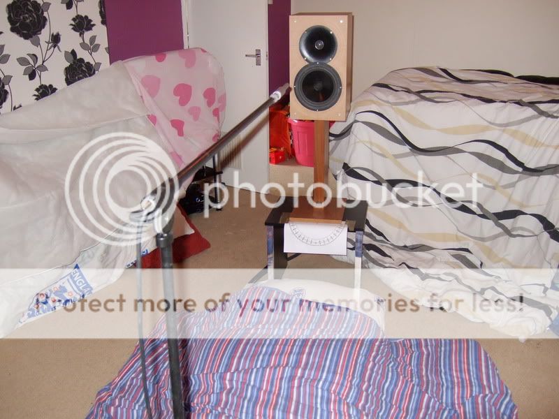
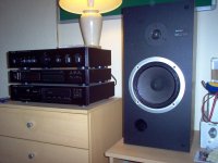
Here's a pic of one before I turned them into floorstanders
Hey system,
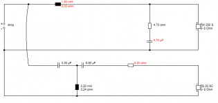
I measured the parts in the crossover.
woofer Inductor = .96mH
Tweeter Inductor = .53mH
Resistor = 2.9ohm
capacitor is 7.21uf
Now with that capacitor does that sound right? going through forums i found that the 4.7uf was being used for the other Jpw speakers. what would be better?
I measured the parts in the crossover.
woofer Inductor = .96mH
Tweeter Inductor = .53mH
Resistor = 2.9ohm
capacitor is 7.21uf
Now with that capacitor does that sound right? going through forums i found that the 4.7uf was being used for the other Jpw speakers. what would be better?
Hey system,
I measured the parts in the crossover.
woofer Inductor = .96mH
Tweeter Inductor = .53mH
Resistor = 2.9ohm
capacitor is 7.21uf
Now with that capacitor does that sound right? going through forums i found that the 4.7uf was being used for the other Jpw speakers. what would be better?
That's good work, my friend. It is, of course an overy simple filter that can be muchly improved. I'll see what I can do with those values, because it saves money. Perhaps fatmarley has a nice circuit you can try too.
An externally hosted image should be here but it was not working when we last tested it.
I find in my archive a similar experiment of my own, so we're in familiar territory.
Attachments

As i am replacing the cap anyway with a poly i ripped the cap off! It is a Bennic 4.7mfd capacitor. any cap brands to look out for? im thinking of going with the jantzen.
An expensive capacitor isn't going to rescue a bad design.
Any 400V polypropylene is going to be quite reasonable here. The tweeter will sound brighter and louder than the original non-polar electrolytic due to lower ESR resistance.
Your 1mH bass, 2.9R and 7.2uF/0.53mH tweeter filter is quite interesting. It has better than usual phase alignment. But a one-trick pony really. I don't like it much overall.
I am still looking at it. 🙂
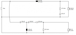
Kermit, I've come up with something you can try here. This is DIY and might need some easy adjustment.
Shopping list:
2X 1mH coils (well actually you have them already!)
2X 1.5mH coils (ferrite will do)
2X 0.2mH aircoil
2X 3.3uF (Polypropylene. 250 or 400V)
2X 4.7uF (You already have these, no?)
2X 6.8uF
2X 2.2R 10W wirewound
2X 3.3R
2X 4.7R
2X 7.5R
2X 22R
With these components I think we can get this working and tweak it to taste. You might as well leave the leads long at the test stage, it's easier soldering/unsoldering.
If you fancy this project, we can talk about the options for tweaking it to taste. It should sound a lot better than your current circuit.
Attachments
Perhaps fatmarley has a nice circuit you can try too.
I haven't at the moment but I may have a go at designing one in the future.
- Status
- Not open for further replies.
- Home
- Loudspeakers
- Multi-Way
- Pls help me ID these JPW Speakers