Hi!
I'm trying to build an op-amp based bass guitar preamp for use with a B&O ICEPower 125ASX2 power amp and I'd really appreciate some guidance and feedback.
I want the preamp to have the following characteristics:
- Single input
- Volume control
- Bass control
- Treble control
- Balanced output (required for using the ICEPower in BTL-mode)
- Be powered from a +/- 15V regulated supply
- Low component count
I'm assuming that an average bass guitar with passive pickups has a max output of 1V peek-to-peek. The ICEPower manual states that the power amp has a maximum input voltage of +/- 3.3V and I'm guessing that this means 6.6V peek-to-peek. This means that I want a net gain of 6.6 from the pre amp with volume at max.
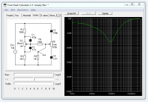
I have experimented with a graphical eq to find a suitable curve and using Duncan's Tone Stack calculator (assuming an output impedance of 100 Ohms from the first op-amp stage) I have designed this curcuit:

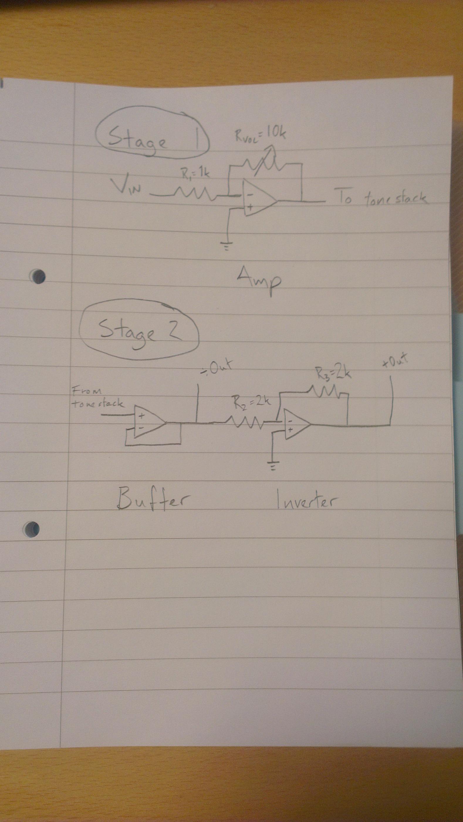
This circuit has a loss of -3db (-0.7X gain) at low frequencies (with bass control at max) and so to compensate for this we need to raise the gain from 6.6X to: 6.6X/0.7 = 9.4X or ~10X (20db). My first attempt at a circuit looks like this:
Questions:
- Are my gain calulations ok?
- Am i running into any impedance matching issues? See the notes on ICEPower input impedance below.
- Are the values chosen (1k + 10k) for R1 and RVOL ok? Would it be better to use 200 + 2k?
The ICEPower power amp has an input impedance of 8k (according to the manual: http://www.icepower.bang-olufsen.co...er125asx2_datasheet_1_1_class_d_amplifier.pdf) or ~26k (according to this guy: http://www.diyaudio.com/forums/atta...easurements-mods-icepower-input-impedance.png)
I hope I've supplied all neccessary details! 🙂
I'm trying to build an op-amp based bass guitar preamp for use with a B&O ICEPower 125ASX2 power amp and I'd really appreciate some guidance and feedback.
I want the preamp to have the following characteristics:
- Single input
- Volume control
- Bass control
- Treble control
- Balanced output (required for using the ICEPower in BTL-mode)
- Be powered from a +/- 15V regulated supply
- Low component count
I'm assuming that an average bass guitar with passive pickups has a max output of 1V peek-to-peek. The ICEPower manual states that the power amp has a maximum input voltage of +/- 3.3V and I'm guessing that this means 6.6V peek-to-peek. This means that I want a net gain of 6.6 from the pre amp with volume at max.
I have experimented with a graphical eq to find a suitable curve and using Duncan's Tone Stack calculator (assuming an output impedance of 100 Ohms from the first op-amp stage) I have designed this curcuit:
This circuit has a loss of -3db (-0.7X gain) at low frequencies (with bass control at max) and so to compensate for this we need to raise the gain from 6.6X to: 6.6X/0.7 = 9.4X or ~10X (20db). My first attempt at a circuit looks like this:
Questions:
- Are my gain calulations ok?
- Am i running into any impedance matching issues? See the notes on ICEPower input impedance below.
- Are the values chosen (1k + 10k) for R1 and RVOL ok? Would it be better to use 200 + 2k?
The ICEPower power amp has an input impedance of 8k (according to the manual: http://www.icepower.bang-olufsen.co...er125asx2_datasheet_1_1_class_d_amplifier.pdf) or ~26k (according to this guy: http://www.diyaudio.com/forums/atta...easurements-mods-icepower-input-impedance.png)
I hope I've supplied all neccessary details! 🙂
Attachments
After doing some research, I've found two flaws in my design:
1) Non-inverting op-amp stages need a DC bias-current return path, so their positive input should be tied to ground using a high-value resistor (effectively determining the input impedance of the stage), ref. Planet Analog - Articles - Avoid common problems when designing op-amp and in-amp circuits.
2) The input-impedance of an Inverting op-amp stage is determined by the resistor connected between the signal source and the negative input, ref. http://zebu.uoregon.edu/~rayfrey/431/notes9.pdf. In my case this means that the bass guitar sees a 1k input impedance, which is way too low, so I need to put a non-inverting buffer as the first stage in the circuit.
After doing some research, I've found two flaws in my design:
1) Non-inverting op-amp stages need a DC bias-current return path, so their positive input should be tied to ground using a high-value resistor (effectively determining the input impedance of the stage), ref. Planet Analog - Articles - Avoid common problems when designing op-amp and in-amp circuits.
2) The input-impedance of an Inverting op-amp stage is determined by the resistor connected between the signal source and the negative input, ref. http://zebu.uoregon.edu/~rayfrey/431/notes9.pdf. In my case this means that the bass guitar sees a 1k input impedance, which is way too low, so I need to put a non-inverting buffer as the first stage in the circuit.
I don't quite see where you get the idea of 1K impedance from?, there's no need for that, design it to ba as you wish.
However, I can't see why on earth you would want to use a passive tone control anyway, which would certainly need a buffer (even though it's fairly high impedance, it needs to be fed from a low impedance source.
Why not just look at what commercial amps do?, or have a look at Albert Kreuzer's FET and opamp design (which is easily alterable as you like).
An active Baxandall is dead easy to do using an opamp. This is the first hit on Google:
They have the advantage of using linear pots, which are much more accurate and easier to get hold of.
You would need an input buffer, but thats no big deal if youre using opamps. You could realise the whole thing using a two opamp chip.
Or, a FET or even bipolar input buffer would be easy to do too.
An externally hosted image should be here but it was not working when we last tested it.
They have the advantage of using linear pots, which are much more accurate and easier to get hold of.
You would need an input buffer, but thats no big deal if youre using opamps. You could realise the whole thing using a two opamp chip.
Or, a FET or even bipolar input buffer would be easy to do too.
Nigel & Mikey: Thanks guys! I'll have a closer look at the Baxandall-circuit and similar active tone circuits.
Nigel: I read somewhere that using high value resistors in the feedback-loop would would introduce noise and that < 10k values were preferable, but maybe my proposed solution of adding a buffer as the first stage will add even more noise?
I'm open for any suggestions. Basically all I want is a high impedance input, 10X gain, a tone control giving a response curve similar to the one in the attached screenshot and a balanced output... 🙂
Nigel & Mikey: Thanks guys! I'll have a closer look at the Baxandall-circuit and similar active tone circuits.
Nigel: I read somewhere that using high value resistors in the feedback-loop would would introduce noise and that < 10k values were preferable, but maybe my proposed solution of adding a buffer as the first stage will add even more noise?
I'm open for any suggestions. Basically all I want is a high impedance input, 10X gain, a tone control giving a response curve similar to the one in the attached screenshot and a balanced output... 🙂
Check out the FET preamp I mentioned, and use just the parts you want - it's trivial to add a balanced output if you really want one (but there's not much point really).
You might get something out of this guy's dissertation on building a bass preamp: Audio, Think Inside the Box.: Bass Guitar Preamp Design
- Status
- Not open for further replies.
- Home
- Live Sound
- Instruments and Amps
- Bass guitar preamp using op-amps