AllenB, I will read your latest post when I'm more relaxed and able to take it in.
In the meantime, I did manage to get a few resistors, what wattages are useful? For example, I've got 3, 5 and 17W resistors and a few more.
Anyone more than me that is contemplating the quality of the test tones used? Is the quality of the test tones of any consequence at all? Even if they are of the same type and frequency, they are not all the same, but if it is worth to bother is what I would like to know, what is the general consensus, if any.
I find that 5W resistors are good to have in many values for testing as they will work in most places. Sometimes 10W resistors are needed in places around woofer crossovers, and sometimes as little as 1W around tweeters. You can simulate the circuits to be sure of the maximum needed, or you can play some music and feel them. You may be able to predict/guess based on their location in the circuit. When I am happy with values, I may try replacing a tweeter series resistor with 1 or 2W carbons as sometimes I get a very slightly different sound compared to a 5W sand cast.
I find that 5W resistors are good to have in many values for testing as they will work in most places. Sometimes 10W resistors are needed in places around woofer crossovers, and sometimes as little as 1W around tweeters. You can simulate the circuits to be sure of the maximum needed, or you can play some music and feel them. You may be able to predict/guess based on their location in the circuit. When I am happy with values, I may try replacing a tweeter series resistor with 1 or 2W carbons as sometimes I get a very slightly different sound compared to a 5W sand cast.
My question about wattage was for a resistor for an impedance jig, does the same aply anyway?
I'll put the diffraction and baffle size questions to rest for now, to much to contemplate. However, if anyone has a tip for a baffle diffraction simulator that does take rounding over the baffle edges into consideration, I'll be happy to hear about it. In the meantime I will check out "The Edge" which is what I have now.
My question about wattage was for a resistor for an impedance jig, does the same aply anyway?
A 1/4-1/2W metal film between 400-1000ohms should do. Use the 1000ohms unless you can't get a large enough signal across the driver.
However, if anyone has a tip for a baffle diffraction simulator that does take rounding over the baffle edges into consideration,
There is one here FRD Consortium called BDS part way down the page on the left.
These are written by enthusiasts and this one is a spreadsheet. It may seem a little clunky at first but it's versatile and will manage chamfers as well as rounding.
A 1/4-1/2W metal film between 400-1000ohms should do. Use the 1000ohms unless you can't get a large enough signal across the driver.QUOTE]
I think I've mentioned earlier that I plan to use an amplifier, then I've heard that a resistor around 10 ohms will do it (as I've seen in a "using LIMP manual" on a native forum. I have a few 10 ohm resistors, and the question is, if they are usable, what wattage would be most suitable? I have 0.25, 3, 5, and 17W 10 ohm resistors.
I'll check that diffraction software out as well.
I do have a question that I've been thinking about for a while. If I am to do a two box tower, how do I treat the two boxes in regard of each other? I mean, I think, at least to start with, I'll give them the same width (12"). Can I treat the two boxes as one common baffle or not? Question is manly in regard of driver placement options in the MTM-box. My thought was that if one can treat the two boxes as one baffle, then I can build the MTM-box shorter (not so high) and still have different distances for the mids to the edges?
And the baffle step correction, the speakers will be much closer to a wall than to "the middle of the room", so is a 3dB correction a "better" starting value?
Well, I assume that the 10 ohm resistor you read about was for calibration. In other words, if you use a 1000 ohm resistor in series with the driver, you first use that 10 ohm resistor in place of the driver to set the levels to something usable, for example 10mV (higher the better within reason) so that 1mV then equals an ohm.
About the baffles, if they are evenly stacked, then yes treat them as one baffle. I'm not sure I understand how differently you are thinking of doing it.
The baffle step is another story. The sound energy will wrap around the baffle but it will still be in the room. It depends on how your room treats this energy. I try to make it so I don't need to apply any specific baffle step treatment. You may need to make some in room measurements, or do some trial and error.
Well, I assume that the 10 ohm resistor you read about was for calibration. In other words, if you use a 1000 ohm resistor in series with the driver, you first use that 10 ohm resistor in place of the driver to set the levels to something usable, for example 10mV (higher the better within reason) so that 1mV then equals an ohm.
About the baffles, if they are evenly stacked, then yes treat them as one baffle. I'm not sure I understand how differently you are thinking of doing it.
The baffle step is another story. The sound energy will wrap around the baffle but it will still be in the room. It depends on how your room treats this energy. I try to make it so I don't need to apply any specific baffle step treatment. You may need to make some in room measurements, or do some trial and error.
No, the resistor is for measurement only when using a power amplifier and the software has a built in calibration feature.
Page 8: http://www.fesb.hr/~mateljan/arta/download/LIMP-user-manual.pdf
I've in vain tried to understand how to connect this jig, and non has come forward on the forum in question, so if anyone can show me how to connect the jig for Limp I'm all ears........ (I mean how to connect the connectors on the jig) (this is what I try to figure out)
HiFiForum.nu - TS-mätningar med LIMP
Regarding the baffle, my plan for now is just to place the MTM-box atop the woofer box with the two baffle fronts lined up vertically, and having the same width. Nothing fancy at all.
I'm still struggling with the baffle step (understanding it and how it influences my results). I'll guess I'll perhaps do comparisons with roundovers and without and possibly try some room measurements as well, when the time comes. I'm currently trying to get the impedance measurements under way, but something is lacking..........................


The 100 ohm resistor and 27 ohm resistor can be small metal films.
I wouldn't go to the trouble of a jig, personally. Take the top (non power amplifier) version for example. Get two patch leads - standard 1/8 headphone jack on one end and two RCAs on the other....and a bunch of alligator clip leads.
Plug one headphone jack into the sound card output and one into the line input. Clip the right output (RCA tip) onto the right input. Clip the left output (RCA tip) to one end of the 100ohm resistor and clip the left input to the other end. Clip the resistor onto the speaker, and then connect the other end of the speaker to the RCA outer ground of the left output lead.
Thank you for this reply. I have the mic lying at the postal office and will pick it up on the way home. and I had just started to think about the possibility to measure without a jig, and here comes you...........
Now I only have to get my hands on a larger resistor (hopefully)
Have I missed something or has buggsson not chosen a woofer yet?
You haven't missed a thing and it will be some time before I get to that point, because I want to measure the mids and tweeters first and get a feel for the MTM part of the system. They will eventually be choosen based on impedance and frequency measurements made by others, and cost, there has to be a limit of some sort.
My primary choice so far, is the CSS SDX10 10".
I'm back
Hi all,
I just wanted to re-open this thread. I am slowly getting out of the black hole I fell inte a couple of years back and I am so waiting for going practial with measuring my MTM-drivers. It's gonna take some time before I can pack up all my stuff. And I have managed to forget most of the little I knew before the black hole.
As I now live in an apartment and have difficulties figuring out a place for far field measurements, can you measure the tweeter and mids using only near field measurements?
It depends your objective. If you intend building an audio system to be listened in the same room, you'll get useful data when measuring at distances like 0.50 meter, 1.00 meter and 2.00 meter.As I now live in an apartment and have difficulties figuring out a place for far field measurements, can you measure the tweeter and mids using only near field measurements?
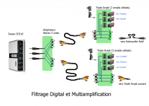
If your music is coming from a Windows PC, you can hook a 8-channel audio card on your PC like a SWEEX SC016 (CM6206 controller) or Asus Xonar U7 (CM6632A controller). You need to use them under ASIO. You will run a Flowstone .exe materializing your preferred digital crossover arrangement. The only specific hardware that's required is a small connectivity panel taking the six audio outputs coming from the audio card, routing them on two triple RCA cables (left 3-way speaker, right 3-way speaker). This way you can bolt the power amplifiers on the speakers. You wife won't complain, as the wires going from the PC to the active speakers, remain like simple wires (actually triple RCA wires).
What's regarding the power amplifiers, you can buy four Lepy LP-V3s stereo amplifiers on eBay (they are based on a TA8254 Class AB IC) and two 14V 60 Watt switching power supplies.
In case you want to experiments with Class C, there are PAM8610 modules available on eBay. You'll be up and running in less than one day.
This is standard, now that Flowstone (helped by VAC and ASIO4ALL) can generate an .exe materializing a digital crossover on a Windows PC.
VAC is mandatory for telling Windows to route the audio, not to the sound card, but to a "Virtual Cable 1" entering ASIO.
VAC licence is inexpensive, and not PC-locked.
ASIO4ALL (to be used on top of the Windows driver that's supplied with the SWEEX SC016) is free.
The only weakness in this, are the long wires (could be 5 meters or more) conveying variable-level audio. This is variable-level audio because your volume controller sits before the wires. The signal/noise ratio will thus degrade, when listening at very low volumes like -30 dB or so. A possibility is to replace the triple-RCA cables by a high quality shielded triple twisted pair (see professional multi-mike cables) driven by three symmetric audio drivers, with differential receivers placed just before the power amplifiers. In most cases, especially when listening in a small living room, you won't need this.
More details on the Flowstone "User Examples" forum.
DSP Robotics Support • View topic - WinXP directly driving two 4-way active speakers
This is now my preferred "Open Source Digital XO" platform.
We are in 2014. Avoid fiddling with audio, without trying this.
Cheers
Attachments
It depends your objective. If you intend building an audio system to be listened in the same room, you'll get useful data when measuring at distances like 0.50 meter, 1.00 meter and 2.00 meter.
Steph, are we talking about the same thing here? I was thinking of the raw drivers but I get the impression you was thinking about the finished boxes. Am I mistaken?
If your music is coming from a Windows PC, you can hook a 8-channel audio card on your PC like a SWEEX SC016 (CM6206 controller) or Asus Xonar U7 (CM6632A controller).
This is now my preferred "Open Source Digital XO" platform.
We are in 2014. Avoid fiddling with audio, without trying this.
Most of my listening is from vinyl but I have ripped all of my CDs to a HD so I'll be listening from my computer as well. However, I stay away from Windows as much as I can and have seen a similar example as you gave for the Macintosh platform. The question is, regardless of system chosen, can I make it? But this is far away in the future, I have to build the speakers first, and before that I have to get my measurement rig up and running.
You can waste 10 days or 10 years measuring raw drivers, before mounting them on a IEC baffle, before bolting them on a box. There will be nice measurements to discuss, indeed, on-axis and off-axis. You'l need another 10 days or 10 years for measuring how you are going to blend it with another driver (woofer, tweeter). Then you'll need to decide about the box geometry, another 10 days or 10 years measurements. Possibly, after 30 years, after deciding about the amplifiers and the cables, you'll be able to start listening to your 2-way system. Possibly your listening room will have changed inbetween. This may add another 10 years. You are in the driving seat.
Pick-up the right tools, and enjoy the journey. The journey I advised is only 1 week. I remain amazed, seeing almost nobody willing to invest one day, setting up the simple Logitech Z-120 equalization (and progressive Linkwitz Transform) experiment using Flowstone. As soon as "unobtainable" stuff becomes available, the value seems to drop to zero, and nobody cares. As soon as "black art" gets exposed using simple words, the value seems to drop to zero. Sorry about that. It's a lesson I'll remember.
Pick-up the right tools, and enjoy the journey. The journey I advised is only 1 week. I remain amazed, seeing almost nobody willing to invest one day, setting up the simple Logitech Z-120 equalization (and progressive Linkwitz Transform) experiment using Flowstone. As soon as "unobtainable" stuff becomes available, the value seems to drop to zero, and nobody cares. As soon as "black art" gets exposed using simple words, the value seems to drop to zero. Sorry about that. It's a lesson I'll remember.
Last edited:
for any diy enthousiast. I would get a reference speaker, commercial or a kit design by a reputable company or designer. you can enjoy and compare to all your diy builds with your referecen
Hi all,
I just wanted to re-open this thread. I am slowly getting out of the black hole I fell inte a couple of years back and I am so waiting for going practial with measuring my MTM-drivers. It's gonna take some time before I can pack up all my stuff. And I have managed to forget most of the little I knew before the black hole.
As I now live in an apartment and have difficulties figuring out a place for far field measurements, can you measure the tweeter and mids using only near field measurements?
Indeed. There are very good speakers available nowadays, for less than 2,000 usd a pair. If you valuate your time at 50 usd an hour, it only makes 40 hours. Most diyAudio stuff consume more than 50 hours to build, measure and finalize, and you still need to buy the parts! Parts that could cost more than 1,000 usd if you obey the gurus. IMO, the only valid strategy is to have fun with inexpensive stuff, relying on top-notch technique. Flowstone. Of course, you need to acquire the required skills. This also takes time. Better invest in knowledge, than in hardware. It lasts longer, and it is funnier. Cheers!
It depends your objective. If you intend building an audio system to be listened in the same room, you'll get useful data when measuring at distances like 0.50 meter, 1.00 meter and 2.00 meter.
So that would be sufficient for the MTM-system?
In case you want to experiments with Class C, there are PAM8610 modules available on eBay. You'll be up and running in less than one day.
I am glad you have high hopes for my ability, but it wouldn't be in one day.[/QUOTE]
You can waste 10 days or 10 years measuring raw drivers, before mounting them on a IEC baffle, before bolting them on a box. There will be nice measurements to discuss, indeed, on-axis and off-axis. You'l need another 10 days or 10 years for measuring how you are going to blend it with another driver (woofer, tweeter). Then you'll need to decide about the box geometry, another 10 days or 10 years measurements.
I have no intention of measuring for an eternity, I hope I will learn how to do it faster than that. I don't want it to take longer than necessary, I've been at building my first system for far too long already.
Pick-up the right tools, and enjoy the journey. The journey I advised is only 1 week.
I am trying to find the tools needed. And one week, my wish, I started eons of time ago and am not started yet. I hope to have my measurement and simulation systems up next week, am dependent on some "hands on" help for getting windows up and running again
IMO, the only valid strategy is to have fun with inexpensive stuff, relying on top-notch technique. Flowstone. Of course, you need to acquire the required skills. This also takes time. Better invest in knowledge, than in hardware. It lasts longer, and it is funnier. Cheers!
If it is funnier, I cannot know yet, but I totally agree that what you say sounds very true. Unfortunately, my head usually is against such thinking so usually I end up with much more expensive stuff than I have a need for. But I hope I can start with more modest equipment then I had intended when I re-started this project.
I have enjoyed myself with re-reading this tread and will try to absorb as much as I can until my computer is up and running again.
IMO, here is very good stuff :
blogohl: Software and VST plugins
The bidirectional IIR Biquad filter used as crossover guarantees a linear phase:
DSP Robotics Support - Bidirectional IIR filter
Speaker Lab enables flattening the speaker magnitude and phase combining a IIR Biquad filter as Linkwitz Transform in as deep bass equalizer, eight IIR BiQuad filters as general purpose equalizer, and a 128-tap FIR filter as high resolution automatic equalizer in the mids and highs:
DSP Robotics Support - Speaker Lab
Flowstone enables you to mix all techniques in a schematic that you'll save as VST plugin (need a VST-Host for loading the VST plugin), or as plain simple .EXE file to be executed after each boot.
Up to your creativity and taste.
Hardware and software cost close to nihil.
You need to tell Windows XP to route the stereo audio (stereo mixer output) to the VST-ASIO world instead of the soundcard. The VST will take care of the soundcard, provided it operates under ASIO. This is explained here:
DSP Robotics Support - WinXP directly driving two 4-way active speakers
In your lab, you can also rely on Flowstone for measuring the impedance of a speaker driver (it generates a text file):
DSP Robotics Support - Speaker Z Meter
Last edited:
IMO, here is very good stuff :
blogohl: Software and VST plugins
The bidirectional IIR Biquad filter used as crossover guarantees a linear phase:
DSP Robotics Support - Bidirectional IIR filter
Speaker Lab enables flattening the speaker magnitude and phase combining a IIR Biquad filter as Linkwitz Transform in as deep bass equalizer, eight IIR BiQuad filters as general purpose equalizer, and a 128-tap FIR filter as high resolution automatic equalizer in the mids and highs:
DSP Robotics Support - Speaker Lab
Flowstone enables you to mix all techniques in a schematic that you'll save as VST plugin (need a VST-Host for loading the VST plugin), or as plain simple .EXE file to be executed after each boot.
Up to your creativity and taste.
Hardware and software cost close to nihil.
You need to tell Windows XP to route the stereo audio (stereo mixer output) to the VST-ASIO world instead of the soundcard. The VST will take care of the soundcard, provided it operates under ASIO. This is explained here:
DSP Robotics Support - WinXP directly driving two 4-way active speakers
In your lab, you can also rely on Flowstone for measuring the impedance of a speaker driver (it generates a text file):
DSP Robotics Support - Speaker Z Meter
I'm going in a similar direction. I've got a pair of Accuton tweeters and 7" Eton low-mids that have been gathering dust for years -- silly, right? Eventually all the rubber and plastics will rot. I think they were originally going into an ambitious 3 or 4-way system, multi-amped with active XOs. But life got busy and I lost interest. And the 2" high-mids were permanently borrowed as replacement tweeters for a 2-way system. Mental note: don't forget passive DC/thump protection.
Now I'm just getting back into it. The active 4-way behemoth/engineering headache will be a much more svelte 2-way with pc-based digital EQ.
I got a pair of these 2x15W class D bad@sses Wzmacniacz z uk?adem TPA3110 - zestaw do samodzielnego monta?u - Sklep internetowy - elektronika i sprz?t DJ and so far they seem amazing, AFAICT with a cheap beat-box. Fortunately, my experimental re-flow oven /frying pan trick didn't kill the TPA3First and foremost, it'll be based on impulse measu110 chip.
The Eton mid-woofer:
Midrange / Bass-Midr. - Home-HiFi - Products - Eton GmbH
will go in an oversized sealed box ~20L, maybe more, that's wide and not very deep. I'm trying to use horn design principles to make it into a sort of mini anechoic chamber, where the backwave gets funneled into a set of horns, but with lower back-pressure than a TL.
In my case I've got Linux and JACK2, so I'll probably end up making or using LADSPA or LV2 plugins for the crossovers, and doing mic measurements with Audacity. I'm not too concerned about IIR filter types, probably end up using FIR or some hybrid to keep delays manageable in the bass. Lots of fun to be had!
- Status
- This old topic is closed. If you want to reopen this topic, contact a moderator using the "Report Post" button.
- Home
- Loudspeakers
- Multi-Way
- Before I start out, I need some direction