Is each coax a signal flow and signal return?
one is the signal and the other one is signal ground.
The signal return is not a ground.
It is the route the current takes that completes the circuit.
The most important parameter of any two wire connection is completing the route back to the Source.
A common reference voltage is secondary to the above primary function.
It helps establish correct grounding if you think of all two wire connections as two wires with a signal FLOW and a signal RETURN.
It becomes even easier if you use a twisted pair for the two wire connection. The oft used "connect the screen at one end" to solve problems would never occur if they had used a twisted pair instead of a coax.
The twisted pair let's your SEE the error in the grounding, whenever you think about disconnecting one end of the Signal RETURN wire.
If you were to adopt screened 2core cable for your two wire interconnections you would solve many of the grounding problems because of the reason stated in the above paragraph, i.e. you would NEVER use the two cores for the circuit connection and then break one of those connections. But you could break the screen connection at one, or both ends and the two wire connection is left intact and the circuit works.
Last edited:
What I did in the end was connect the two shields together (rca side) and the to the chassis, leaving disconnected the board side.
I'll be finishing my F5v3-projekt soon,
and I'm still in doubt if my power supply will fit.
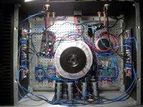
instead of the suggested version I am using the 500VA/2x21V transformers secondarys center tap directly as mainaudioground. this gives me 2 x pos/neg out of two bridge-rects with diodes paralleled
by 3.3nF foils. followed by a crc filter with 12 x 22,000µF plus snubbers and bleeders.
so, are there any pros or cons regarding the ground and or the resulting 29V supply-voltage?
http://origin.dastatic.com/forums/gallery/data/500/Bildschirmfoto_2014-05-10_um_16_31_29.jpg
and I'm still in doubt if my power supply will fit.
instead of the suggested version I am using the 500VA/2x21V transformers secondarys center tap directly as mainaudioground. this gives me 2 x pos/neg out of two bridge-rects with diodes paralleled
by 3.3nF foils. followed by a crc filter with 12 x 22,000µF plus snubbers and bleeders.
so, are there any pros or cons regarding the ground and or the resulting 29V supply-voltage?
http://origin.dastatic.com/forums/gallery/data/500/Bildschirmfoto_2014-05-10_um_16_31_29.jpg
use generic FW PSU ( visible in , say , F5 article ) with split secondaries , two bridges and gnd made after bridges
reinventing the wheel is ending good only when you know what you're doing
reinventing the wheel is ending good only when you know what you're doing
thanks for the quick reply, zen mod
is noise from the transformers secondarys the purpose for keeping the zeropoint separated via the bridge?
my idea was to have the power for each channel easily splitted right after the transformer.
is noise from the transformers secondarys the purpose for keeping the zeropoint separated via the bridge?
my idea was to have the power for each channel easily splitted right after the transformer.
besides it's not my invention, there is an example for the ground taken straight out of the transformer by his highness himself -> http://www.firstwatt.com/pdf/art_f5_turbo.pdf
further down the page is a power supply for an F5turbo
further down the page is a power supply for an F5turbo
all roads are leading to Rome
which one you'll choose is matter of compromises you choose
most important thing with two bridges/gnd after them is avoidance of any DC imbalance going trough secondary
which one you'll choose is matter of compromises you choose
most important thing with two bridges/gnd after them is avoidance of any DC imbalance going trough secondary
I got a weird question, a bit OT. I am an old tube guy and I use solder tag strips all the time.
I am dipping my toes in the F5 realm and...
I notice on all of these SS builds there is a tendency to use screw terminals and such; is there a specific reason?
Like on the previous page of posts there is a pic where the CL-60 are on a screw terminal strip.
I use CL-120 often in tube builds and always use a solder tag strip - I just see it as more secure...
Can one of you that are more experienced than I in the ways of sand shed some light?
if the question is "soldering or screwing"
i'd suppose the second is more fun but less safe or as np once wrote
"solder connections where possible"
i'd suppose the second is more fun but less safe or as np once wrote
"solder connections where possible"
Alles Klar....
So what your sayin is one may be more fun but the other is safer in the long run😉
So what your sayin is one may be more fun but the other is safer in the long run😉
Mechanical securing is more reliable than low temperature soldering when operating temperatures approach the melting point of the solder !
But I doubt that's why builders adopt screws. It is more likely that screws allow repeated dismantling to experiment with layout/s.
But I doubt that's why builders adopt screws. It is more likely that screws allow repeated dismantling to experiment with layout/s.
When the thermistors are not properly mechanical secured before soldering they can get so hot that they might desolder themselves. Maybe that's why.
When the thermistors are not properly mechanical secured before soldering they can get so hot that they might desolder themselves. Maybe that's why.
I can't imagine any component inside an F5 getting hot enough to de-solder itself😱
What kind of solder are we talking about?
low temperature solders melt at temperatures below the maximum temperatures of many semiconductors. Flow soldering and hot air gun soldering are examples of manufacturing temperatures well above normal operating temperatures. Semis can survive very high temperatures.
An NTC is intended to run hot.
Pass a mains fault current through it and it will run even hotter.
Expect it to de-solder itself in event of a catastrophic fault.
An NTC is intended to run hot.
Pass a mains fault current through it and it will run even hotter.
Expect it to de-solder itself in event of a catastrophic fault.
Another thought on screw terminals and NTCs. I use the typical Euro style strips and insulate the leads coming out of the strip with insulation PVC stripped from hookup wire. The ends of the insulation nearest the NTC tend to melt a bit.
On one build I didn't use the PVC since it was melting. The terminal strip was mounted to the 4U store case baseplate and the NTC arced to the base on startup. I cut the leads as short as possible and it still arced. Sort of a fireworks style splatter rather than a damaging arc. Temporarily solved with a bit of kapton tape on the baseplate, but I will insulate the leads with teflon before the adhesive loses its grip.
I suppose this also says we should add some insulation under the mains terminal strips if we are mounting to a grounded baseplate.
ApexJr sells a nice assortment kit of heat shrink tubing where the smallest size also works well insulating leads.
hum...
Hi guys, now it's the last step. Facing the hum. I can hear it clearly on both channel and when I connect the rca cable it becomes louder. The only way I found to limit it is connect with a wire the L rca gnd to power supplu gnd. But it is still there. Any suggestion?
Hi guys, now it's the last step. Facing the hum. I can hear it clearly on both channel and when I connect the rca cable it becomes louder. The only way I found to limit it is connect with a wire the L rca gnd to power supplu gnd. But it is still there. Any suggestion?
Attachments
- Home
- Amplifiers
- Pass Labs
- F5 power amplifier