So, Juan: you are able to draw "rounded" PCB-tracks?! 😛
Never mind - find attached a very simple "Soft- Power-On - PCB", which can be used by 115VAC primary DIYers and 230VAC primary DIYers as well.

http://abload.de/img/topviewxroh7.png
Best regards - Rudi_Ratlos
P.S.: This layout has been done with the EAGLE-educational software, since it is < than 100x100mm.
Last edited:
Yes Rudi jejejejeje I'm trying different styles of PCB layouts styles there are many way to do things and I'm trying to polished myself a bit more 🙂
can I use that for any amplifier project ? it will be nice to turn on a amplifier with out using a toggle switch sound "clack"
Regards
Juan
can I use that for any amplifier project ? it will be nice to turn on a amplifier with out using a toggle switch sound "clack"
Regards
Juan
Last edited:
Concept from Willie extended 2
Willie I'm using your reference to see if I can make a good one I still not sure if I want the coil on the board maybe I will place it away from the circuit , also I want to keep tracks no so short nor to long is way too difficult any way this is just practice 😀 .
moderators can you remove post #83 when you get a chance please
image upload fail this is the image that fail that day.
Regards
Juan
Attachments
Last edited:
Concept from Willie extended 2
Willie I'm using your reference to see if I can make a good one I still not sure if I want the coil on the board maybe I will place it away from the circuit , also I want to keep tracks no so short nor to long is way too difficult any way this is just practice 😀 .
Mister moderators can you remove post #83 when you get a chance image upload fail this is the image that fail that day.
Regards
Juan
Look very nice bro... Have fun!
Regards,
Look very nice bro... Have fun!
Regards,
thanks man 😀
best regards
Juan
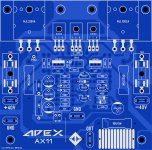
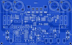
Well today I'm almost done with the layout basically is mister Miles AX-14 with mister Willie reference it came out a little weird looking I have to try again 🙂 anyway this is for fun thanks Willie 😀
do not mind about possible errors I still checking the layout
best regards
Juan
do not mind about possible errors I still checking the layout
best regards
Juan
Attachments
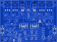
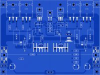
Ok here is the AX-11 BETA board I'm not sure about living the coil on the board maybe I will make a separate circuit to avoid having the nasty magnetic fields away from the circuit but I guess since this will not generate so much the AX-11 is rated at 100W I will not run the amp to the clipping jejejejeje well this is one I have more versions to make also B500 from mister Miles Apex
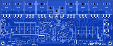
"yes I know I'm coping the already made layouts but that is the best way to learn jejejejeje" here is B500 but I'm not sure if leave it in that "top mount style transistor installation way"
also here is wow I don't know what happen here AX-14 uhmmm not sure about this one 😀
This is just concept ideas not really test it, only for "figure out styles reference"
the B500 and PA protect AX-14, AX-11 layouts belongs to mister Miles Apex.
best regards
Juan
Attachments
Last edited:
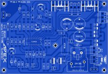
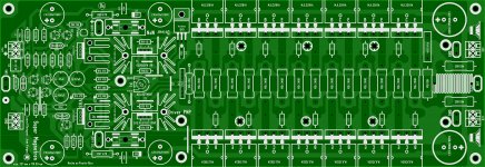
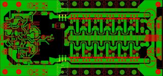
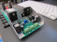
Here I have "Supermagnetron" is a prototype I have not test it yet but I have intentions to try out this year "maybe next" is basically a Class AB amp noting special but sure look good I hope you guys like it 🙂
And no, I will continue learning as always 😀
Regards
Juan
And no, I will continue learning as always 😀
Regards
Juan
Attachments
Juan you are an artist really. Keep up the great work bro.
Regards,
Aniket
thank Aniket I have many but many things I wan to do but wow is a lot 😀
Regards
Juan
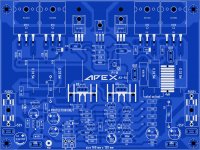
On the layout I have to make some changes because the board is way to long for me to printed out for prototype so what I did is I remove one pair and make it a bit less longer I also make it wider the original will remain the same with 7 pairs.
Juan
Juan
Attachments
Hi Juan
I'm no expert so please take my comments with a "grain of salt".
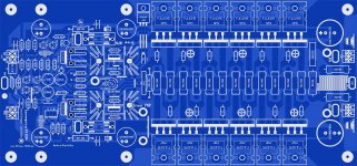
- I like the nice big 1000uF decoupling caps: a big amp like this needs some decent local decoupling. If you can make room then consider laying it out to accommodate 22mm snap in caps with 10mm lead pitch, which would allow up to 2200uF using 100V caps.
- Consider a single 10R / 5W resistor at the output coil instead of the 2x 20R / 5W, which will be more difficult to source and take up more space.
- Have a look at Pete's power rail "bus bar" concept in his thread: http://www.diyaudio.com/forums/solid-state/248105-slewmaster-cfa-vs-vfa-rumble.html If you put lay some pads to solder a length of heavy gauge wire to the PCB, there won't be a large voltage drop as a result of thin and narrow PCB tracks
- Those TO-220 drivers are going to be stressed driving 7x outputs. Suggest that you use 2SA1943/2SC5200 (or similar) instead. Rather than mounting them to those board mounted heatsinks, which take up a lot of space, consider placing the drivers side-by-side so they can be attached to a piece of aluminium flashing or plate. Simple, inexpensive and saves board space.
- You may need to increase R25 to 180R or even 220R to keep driver dissipation manageable at those rail voltages.
- I would move the power input faston connectors and fuses to the other side of the PCB, closer to the output transistors and filter caps.
- You could remove C18 and C21.
I'm no expert so please take my comments with a "grain of salt".
- I like the nice big 1000uF decoupling caps: a big amp like this needs some decent local decoupling. If you can make room then consider laying it out to accommodate 22mm snap in caps with 10mm lead pitch, which would allow up to 2200uF using 100V caps.
- Consider a single 10R / 5W resistor at the output coil instead of the 2x 20R / 5W, which will be more difficult to source and take up more space.
- Have a look at Pete's power rail "bus bar" concept in his thread: http://www.diyaudio.com/forums/solid-state/248105-slewmaster-cfa-vs-vfa-rumble.html If you put lay some pads to solder a length of heavy gauge wire to the PCB, there won't be a large voltage drop as a result of thin and narrow PCB tracks
- Those TO-220 drivers are going to be stressed driving 7x outputs. Suggest that you use 2SA1943/2SC5200 (or similar) instead. Rather than mounting them to those board mounted heatsinks, which take up a lot of space, consider placing the drivers side-by-side so they can be attached to a piece of aluminium flashing or plate. Simple, inexpensive and saves board space.
- You may need to increase R25 to 180R or even 220R to keep driver dissipation manageable at those rail voltages.
- I would move the power input faston connectors and fuses to the other side of the PCB, closer to the output transistors and filter caps.
- You could remove C18 and C21.
hello Ranchu
I will check that out about slewmaster -cfa subject
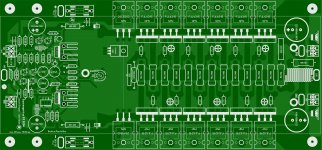
that is a good idea about having the drivers to the sides of the PCB i WILL MAKE those changes I already remove C18 and C21 and change R25 to 220R and I remove one of the 20 ohm resistors from zobel now what I have in mind is what where to place Q19 and the fuses 🙂
Regards
Juan
I will check that out about slewmaster -cfa subject
that is a good idea about having the drivers to the sides of the PCB i WILL MAKE those changes I already remove C18 and C21 and change R25 to 220R and I remove one of the 20 ohm resistors from zobel now what I have in mind is what where to place Q19 and the fuses 🙂
Regards
Juan
Attachments
Last edited:
I am glad to see you are having fun Juan
Nice work you have done.... the pcboards you made to the Dx Super A is a work of art..no one could make it better.🙂
regards,
Carlos
Nice work you have done.... the pcboards you made to the Dx Super A is a work of art..no one could make it better.🙂
regards,
Carlos
Nice work you have done.... the pcboards you made to the Dx Super A is a work of art..no one could make it better.🙂
regards,
Carlos
thank man I'm happy to help the best I can 😀 this might take some time but the must important thing is to have fun with it

Regards
Juan
- Status
- Not open for further replies.
- Home
- Amplifiers
- Solid State
- Dx Juan layouts ideas PCB