Harman Kardon Citation II - my rebuild thread
Hello audiophiles...
I have a Harman Kardon Citation II amplifier that I wish to rebuild.
A little history: I found it in an estate sale about 12 years ago. At the time I was taking classes in basic electronics, and I had help from an instructor who was very familiar with tubes (WWII radio man). When the bias winding is connected, it hums like a chocolate bunny filled with jumping beans. I managed to limp it into life after replacing the top hat diodes with NTE5814 (overkill I know, I like safe rather than sorry and they fit in the holder nicely) and using a secondary transformer to run the bias but the tubes would always end up glowing hot after about 30 minutes of playing. Between moves, smashing some of the old 12BY7's, it has ended up just being a floor anchor. Now some years later I have a pair of Logan Martins that I'm DYING for this thing to run.
I have been reading THOROUGHLY through the QuadESL and Jim McShane sites, forums, google, etc and I stumbled across Carver's Hotrod edition. That is what I want to build!
So my plan is:
Full rebuild replacing all resistors with modern carbon film resistors, all 5% tolerance. (I notice the Deuce uses a TON of 10% resistors on the schematics)
Recap the entire unit with as much capacitance as I can cram on that board for a reasonable amount of money (10-20% more than the McShane kit, but using more common brand caps)
Fresh tube set - have a matched sextet of 12BY7A RCA black plates ordered already, will order KT120's closer to end of build (the stock 6550's are still testing good and will allow me to test first)
DC restorer circuit, change Bias resistors to bring the tube bias current WAY down, and current inrush limiters to be installed, change transformer taps to take advantage of the extra power available in the KT120's
I am doing this rebuild on an EXTREMELY tight budget, but not so tight that I am willing to skimp on necessary items.
First I'd like to ask anybody thats done a Deuce rebuild or modifications for any advice they would offer someone doing their first rebuild.
Second is I need help with the schematics. I have sifted through the entire internet (see for yourself, The Last Page of the Internet ) and I have found only one schematic that is supposedly the key to the KT120 upgrade. If Bob Carver is listening (or anyone that knows), is this all that needs to be done for the KT120 upgrade on the Deuce?
Thanks
Caleb
Edited to change the title since this is becoming a documented rebuild
Attachments
Last edited:
You've already found a couple of sites that have good information on restoration of the Citation II. Jim McShane is a great resource and you'll save yourself a lot of time and trouble if you use his power supply rebuild kits. They're very good.
Rather than replace every resistor, I'd measure the ones in your amp and only replace the ones that are out of spec. I'd also start by restoring the amp to more or less original condition. That would be less work and would be a "known" reference so if you have any problems you can be sure it's not the design. And it would be good to listen to the original version and see if you like it - you might not feel a need to go any further.
Finally, I'm worried about your comment about replacing the top hat diodes with 1N4148 diodes. Those diodes are not suitable replacements since they only handle 100v reverse voltage. Perhaps you typed in the wrong part number?
I've got a Citation II that I've restored and think it's a great amp.
---Gary
I should have clarified, I don't intend to do everything in one step... First replace all the bad parts and inrush limiters, lower the bias current, and get it running. Little later, do a recap/upgrade, and get it running. Rebuild the turret boards and replace all the other resistors floating around the chassis, then get it running. Once it is in tip-top stock shape if I still want more I'll start the KT120 upgrades. I'd like to get it working properly soon, but I'm not in a hurry to get the KT120's in. However, I am already sure I'll want the upgrade before it becomes a permanent fixture in my rack.
I stumbled across Carver's Hotrod edition. That is what I want to build!
It's your amp, but I strongly recommend you NOT do the Carver stuff.
So my plan is:
Full rebuild replacing all resistors with modern carbon film resistors, all 5% tolerance. (I notice the Deuce uses a TON of 10% resistors on the schematics)
Changing resistors just for the sake of the 5% tolerance is a waste of time and money. Changing to replace out of spec resistors or installing resistors more appropriate for their use in the circuit is a good thing to do. Also, there are better choices than carbon films for a number of resistors.
Recap the entire unit with as much capacitance as I can cram on that board for a reasonable amount of money (10-20% more than the McShane kit, but using more common brand caps)
Huh?? More common brand?? More common than Panasonic, F&T, JJ?? And there are issues that arise with adding capacitance. I've got them sorted out, but if you want to do this on your own I just suggest you be VERY careful.
Fresh tube set - have a matched sextet of 12BY7A RCA black plates ordered already, will order KT120's closer to end of build (the stock 6550's are still testing good and will allow me to test first)
DO NOT use KT-120s!! They draw TOO much heater current and will cause trouble. The power trafos are at least 50 years old, and there is already an issue on some with the bias winding. Don't put more stress on them!
DC restorer circuit, change Bias resistors to bring the tube bias current WAY down, and current inrush limiters to be installed, change transformer taps to take advantage of the extra power available in the KT120's
Well, as I mentioned above I'd avoid the Carver stuff. But as I said it's your amp.
I am doing this rebuild on an EXTREMELY tight budget, but not so tight that I am willing to skimp on necessary items.
Okay. But realize that the Cit II is the equivalent of a Corvette, not a Vega. Some things simply cost more on the Deuce. And it's easy to overspend, investing a lot of money in things that don't make a meaningful improvement.
First I'd like to ask anybody thats done a Deuce rebuild or modifications for any advice they would offer someone doing their first rebuild.
This may sound self-serving, but why reinvent the wheel? You can get everything you want for the amp (except the Carver stuff) in the marketplace now, all tested and fully proofed, with a long track record of durability and reliability and support. Instead of all the fooling around, IMHO you need to spend the money you have on new octal (and maybe 9 pin) tube sockets, new wire to replace the crispy 50 year old PVC insulated stuff, new RCA females to replace the corroded originals, a reworked bias supply to eliminate the potential intermittent loss of bias voltage I mentioned above, new speaker terminals, new AC balance pots to replace the corroded originals - and so on.
If you want to hot rod the original circuit you can do it - but FAR more effectively than you've planned and with no risk to the power trafo.
Second is I need help with the schematics. I have sifted through the entire internet (see for yourself, The Last Page of the Internet ) and I have found only one schematic that is supposedly the key to the KT120 upgrade. If Bob Carver is listening (or anyone that knows), is this all that needs to be done for the KT120 upgrade on the Deuce?
Again IMHO, installing the KT-120s in a Deuce is a regression, not an upgrade.
If you need schematics, voltage charts, etc. they are on my site - but no Carver stuff. Bob and I get along great, we do swap emails form time to time, and he's purchased a number of my kits and reproduction knobs for his Cit I collection from me over the years. But as I told him, I believe his Cit II stuff misses the mark, I think we've pretty much agreed to disagree. My bench tech comrade Don Sachs has had to repair a number of "Carverized" amps and preamps, and Don didn't like what he saw at all. The Carver Citation I moving coil mod is worth a try if you like - it's cheap and risk-free and with a quiet enough pair of tubes it works well - but I don't recommend the amp stuff.
Hey, but what do I know, I've only been working with these amps for 35 years... I have a ton of experience with these amps - and while there is a LOT I don't know in the audio world, I DO know these amps. And I've done my best to make stuff available for them that works and that I can provide help with.
In any case, good luck with your project.
Jim, since you have some insights into Carver's thinking, I wonder if you know what the rationale is for converting to pentode and at the same time removing the local feedback loop from the output tubes' anodes. It seems on first glance that this would raise the source impedance to the output transformer, which is not conducive to low distortion.
Jim, since you have some insights into Carver's thinking, I wonder if you know what the rationale is for converting to pentode and at the same time removing the local feedback loop from the output tubes' anodes. It seems on first glance that this would raise the source impedance to the output transformer, which is not conducive to low distortion.
Hi SY,
Based on the conversations we had, my impression was all he cared about was reducing the bias current and increasing the output power. The conversion to pure pentode was (again, based on my impression) apparently based on the fact that Stu Hegeman had told Bob he didn't really like U/L, and it was a mistake to use it - that's why he didn't use it in the Cit V. So that's why Bob wanted to do the Deuce in pentode I think.
Bob never really mentioned to me why he felt the local loop should be removed. I never really thought to ask either. Clearly it changes a lot about the amp including the distribution of the total NFB - without that local NFB the amp would have higher global NFB - maybe that helped to linearize the amp more after all the changes he made, I don't know.
That's about all I can tell you.
Holy mother! God (I mean Jim McShane) spoke back to me!
Thank you for your reply, I have been following your work for quite a while... and I'll be the first to say, I'm an amateur in comparison.
To clarify about the the capacitors, I do mean things like Panasonic, Nichicon, etc. The ROE Gold, J&J, Audiophiler, et al. will elevate the cost of rebuild out of what I can reasonably afford. Seems to me that you believe in the philosophy of "More is better" on the caps, so it only made sense to me to take it a step further. I'm not negating any of your research, just trying to build/continue upon it.
I am NOT an "Old school" tube person, I didn't grow up in it. The Citation sounded AMAZING when it worked (even though it was probably only working half right). It got me into tube audio in the first place. Any improvements I make on my baseline will be impressive TO ME. Maybe not the guy who has a rack of Mcintosh equipment with NOS KT88 Gold Lions, but to me if it blows away my mid-grade Pioneer surround receiver then its a MASSIVE improvement and I can always improve it again if my tastes grow more discerning.
Jim when I saw that you'd replied to my page, I KNEW before I'd read it that you were going to say "NO NO NO NO!!!" on the KT120's. I doubt my dreams will come true and the other gods (Stu and Carver) will come to defend the KT120, but you are a legend... what is lost in that upgrade that turns you against it? You said there have been some Carver-ized deuces in your shop for repair... whats going wrong? My biggest concern is that 60WPC is going to be swallowed whole by my electrostats. 110W rms of transistor can't even satisfy them! The amp is crackling like pop corn just before I get it turned up to the "Sweet spot" volume. If you know some alternatives to get the extra power needed out of the deuce without the tube upgrade, PLEASE share!
I should have clarified, I don't intend to do everything in one step... First replace all the bad parts and inrush limiters, lower the bias current, and get it running. Little later, do a recap/upgrade, and get it running. Rebuild the turret boards and replace all the other resistors floating around the chassis, then get it running. Once it is in tip-top stock shape if I still want more I'll start the KT120 upgrades. I'd like to get it working properly soon, but I'm not in a hurry to get the KT120's in. However, I am already sure I'll want the upgrade before it becomes a permanent fixture in my rack.
Caleb,
I can promise you that the "bad parts" include almost all of them, especially the power supply. You are doing the equivalent of overhauling the carburetor on an engine with worn out piston rings. Or putting new windows in a house that has a crumbling foundation.
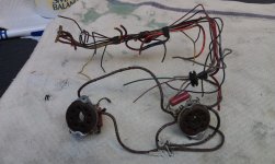
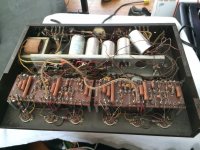
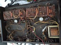
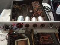
In a 50 year old amp that ran hot and made pretty high power the power supply is shot, the wiring is old and crispy, the AC pots are internally corroded, 50% or more of the resistors will have drifted out of spec (and more will be damaged during the replacement of other parts), the original steel RCA females are corroded, the stock speaker terminal strips are corroded, the tube sockets (especially the octals) are worn and corroded, the coupling and compensation caps are tired, the internal shielded wire may be black inside, the stock bias meter is seriously inaccurate, the meter selector switch is corroded, and the amp is filthy inside. Other than the magnetics, the terminal boards themselves and the bias pots (which need CAREFUL disassembly and cleaning!) and a few bits of hardware are about that you all you can save if you want the amp to be reliable in the future. Take a look at the wiring and the socket I removed from a Deuce not long ago (pics below). Do you want that in your amp?
In order of priority the first thing I recommend on a Deuce is the power supply be redone, then the octal sockets and screen/cathode resistors replaced, then the bias supply repair/upgrade. Do those first as well as change any obviously failed items and the amp will be fairly safe to use. But it will fail even with that done - it's not a question of if, it's a question of when. And with the original power supply the failure will be in the NEAR future, and could be quite expensive.
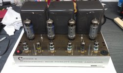
But when it's done, it can be like the other pics I attached!
Attachments
Panasonic and Nichicon capacitors are quite reasonably priced at Digi-Key, etc. A little care in sourcing will save you time, trouble and money later. Most cheap no name caps these days are not particularly trustworthy.
I'd be a little ashamed to take pics of my deuce right now Jim... I actually already have replaced the RCA in's, and replaced 2 of the screen/cathode resistors. One of the power supply caps exploded when I did my first plug in so one cap has been swapped with a NOS paper can but it does work. I do have some terminal plugs already (nice heavy ones) that I'm going to mount in a fiberglass strip. I guess I neglected to mention some of the items I intend to do, I just considered it assumed I guess.
The tube sockets look decently ok, I cleaned them really good and they look clean on the inside. (tooth picks, kabobs, distilled water and compressed air)
Thanks for the tip on the pots... I've taken quite a few switches apart (the most interesting ones come in cars) so cleaning the existing ones shouldn't be too difficult. I would love to retain as many existing components as possible as long as they are in good working order.
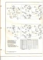
change the bias pots to 25k. R29 may need to go to 47k
this will increase the negative bias voltage allowing lower plate bias current
be sure to to on amp with bias pot wiper to max negative voltage as this will set the minimum plate current.
only replace the large caps
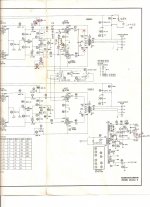
do not change any feedback parts until it is running. The amp is using an unbalanced driver stage to the output as evidenced by the 12k (R17) plate resistor and the 4.7k + 8.2k (R18 & R23) resistors with output tapped between them
this will increase the negative bias voltage allowing lower plate bias current
be sure to to on amp with bias pot wiper to max negative voltage as this will set the minimum plate current.
only replace the large caps
do not change any feedback parts until it is running. The amp is using an unbalanced driver stage to the output as evidenced by the 12k (R17) plate resistor and the 4.7k + 8.2k (R18 & R23) resistors with output tapped between them
CBox,
The first thing I'd do, is start at Jim McShane's site and reread everything
he has.
Then, I'd start by doing his recommendations first.
Post pics of your amp to start or before you start so we can
see what you are starting with. Be cautious as you desolder and
ensure you vent the vapors outside, start your exhale process
when your iron touches the tab.
Shame on me, I should have read before posting.
Hey Jim, they tell me this is THE year for the Cubbies?
Is it true that Johnny Footboll made his visit to Halas Hall?
Probably get it going first, then make incremental changes.
Maybe Jim will chime in here. Also Kevin Kennedy hangs out
here too.
Jim's site is a wealth of information. And yes I followed his (McC) information and currently my CitationII runs in Triode mode. : )
Thank's Jim, BTW I'm finally getting around to finishing up the
pre.
Post Pics and keep us posted.
Last edited:
change the bias pots to 25k. R29 may need to go to 47k this will increase the negative bias voltage allowing lower plate bias current be sure to to on amp with bias pot wiper to max negative voltage as this will set the minimum plate current.
With all due respect, this is not good advice. There is no need to change the value of the bias pots - which is good since the original dual pots can usually be cleaned up and reused reliably. There are ZERO exact replacements to be had. And finally, the larger value the pots are the harder it is to get good resolution when adjusting bias.
In the kits we provide (2) 4.7K resistors to replace R26 & 61. When the bias supply is rebuilt properly (which includes larger filter caps) that is all you need to do to the supply. Replace the cathode resistors with 18 Ohms (instead of 15 Ohms) and the bias will be about 83 ma. when the meter is at the bias mark - assuming the meter is working properly and its scaling resistors haven't drifted too much.
only replace the large caps
Why only the large caps? And which large caps do you mean? What cap(s) do you recommend retaining after 50 years of service??
do not change any feedback parts until it is running.
Do not change any feedback parts - PERIOD!
The amp is using an unbalanced driver stage to the output as evidenced by the 12k (R17) plate resistor and the 4.7k + 8.2k (R18 & R23) resistors with output tapped between them
But you neglected to mention there is an AC balance pot in the circuit ahead of the resistor(s). The PI/driver stage is a long-tailed pair, and it was/is common practice to use slightly different plate load values in them.
Again, I don't mean to try to be Mr. Know-It-All, but I really couldn't NOT reply to this post. Thanks for pitching in, but I think other approaches will solve the problem better.
CBox,
The first thing I'd do, is start at Jim McShane's site and reread everything
he has.
Then, I'd start by doing his recommendations first.
I obviously agree - and they wouldn't be my recommendations unless I knew what I was talking about.
Hey Jim, they tell me this is THE year for the Cubbies?
HA! In the words of Michael Jordan - when he was explaining why he left the Bulls rather than try to stick around for rebuilding - "look at the Cubs - any team can have a bad century!"
Is it true that Johnny Footboll made his visit to Halas Hall? Probably get it going first, then make incremental changes.
Sorry, no comprende!
Jim's site is a wealth of information. And yes I followed his (McC) information and currently my CitationII runs in Triode mode. : )
Thank you for the kind words!
Thank's Jim, BTW I'm finally getting around to finishing up the
pre.
Cool, it'll be a great addition to your system.
CBox - Jim is just being modest. He saved my CitationIIs arschen, beide them.
He knows what is talking about and has decades of experience optimizing the CII.
Before you go off into never never land, or the milky way (as E., Deming used to say),
try Jims upgrades first. Then when stabile and working if you to fool around
do that later.
Save the money upfront, only do what needs to be done. There is plenty of work
in a CitII and it's not as bad as say working on the cheapo SMD mixing boards.
Hopefully so. I really want to get it going using vinyl too.
Been only slightly more than a decade sitting under a shelf on my bench.
What do you recommend for the cartride side? Going to start with one
the MM cartridges. To start at least with a Red M that's gotten some
good reviews from Needle Doctor. Thoughts?
FYI - Johnny Football, Heismann winning QB from Texas A&M, two years ago.
First Frosh winner. He is absolutely the best player I've seen since
I saw Gayle Sayers play.
He knows what is talking about and has decades of experience optimizing the CII.
Before you go off into never never land, or the milky way (as E., Deming used to say),
try Jims upgrades first. Then when stabile and working if you to fool around
do that later.
Save the money upfront, only do what needs to be done. There is plenty of work
in a CitII and it's not as bad as say working on the cheapo SMD mixing boards.
Cool, it'll be a great addition to your system.
Hopefully so. I really want to get it going using vinyl too.
Been only slightly more than a decade sitting under a shelf on my bench.
What do you recommend for the cartride side? Going to start with one
the MM cartridges. To start at least with a Red M that's gotten some
good reviews from Needle Doctor. Thoughts?
FYI - Johnny Football, Heismann winning QB from Texas A&M, two years ago.
First Frosh winner. He is absolutely the best player I've seen since
I saw Gayle Sayers play.
Last edited:
Thanks everyone for the advice... Jim, I'm going to start rebuilding the power supply section and bias section, and start prodding around for bad/out of range resistors. Basically all that you told me. Thanks for the advice on everything. If I had the $dough$ you rightfully deserve, I'd send it off to you in a heartbeat and let you work whatever magic you wanted on it. Since I don't, the least I can do is say is thank you.
Question still stands though, would you still add more capacitance over your top-end kit given you were doing it from scratch or is there a reason you stopped where you did?
BTW I wanted to ask... I don't trust the meter for sure. Isn't there a way I could measure with a multimeter to verify the results? I've got a fairly nice Fluke meter.
Thanks
Caleb
I'll post some pictures once I get it up on the bench. I know you're no stranger to how heavy this &%$# thing is!
Any thoughts on the Fisher 400-C preamp? I managed to become the lucky owner of one of those when I got the deuce...
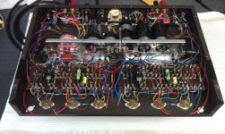
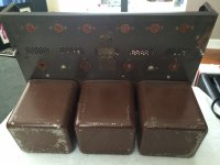
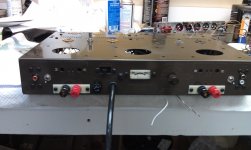
Here's the amp, and the new speaker connectors I have for it... nice and heavy duty. None of the amp looks like its been run crazy hot, the wires all still have a nice color to them (I'm not excusing replacing them, they're gone... just saying)
Its been quite a while so I'd forgotten a bit of what I'd done to it in past years. I removed the fuse holder from the front and changed to an internal holder so I could get the toggle switch in. Also since that cap is a paper can I never properly mounted it, it was never intended to be permanent.
I also remembered that I haven't replaced the RCA's, I remember now just cleaning them really well. I had machine tools at my disposal back then so when I did it the steel was polished inside and out like a mirror. They're still getting replaced, but it made them work really well at the time. Also bent the internal connection tighter. Worked for the time
Attachments
Last edited:
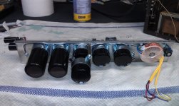
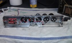
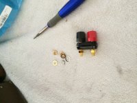
I removed the fuse holder from the front and changed to an internal holder so I could get the toggle switch in.
Remove the AC "convenience" outlet and you can fit a healthy DPDT slide switch in that spot. That way the fuse can stay in the original back panel location where it belongs. Check the pic I attached.
Attachments
I had forgotten all about the convenience outlet. I remember taking it out because it was broken. Stop adding to my shopping list Jim! *LOL jk*
If something blows a fuse, I'm going to take it apart and find out why anyway... especially with my deuce. I don't mind the fuse being indoors.
BTW, I found a couple nicer Nichicon 140uF 450V caps in my parts bin. They're not quite as big as I was expecting (looking at tube parts I forget how much they have shrank over the years). Small enough that I was going to use them and install them on the turret board so I could do away with the dual section cap for V1/V4 - kinda like you did with the Bias caps (but with a grounding board). That means I got 2 free spots for caps, or room for some digital circuitry i.e. separate DC heater supply to help out with my already weakened power trans, tube illuminating LED's, timers for powering up the heaters before B+, LED power button, etc... but no digital audio mods. My projects tend to dream bigger than they get...
I took both of the back panel bias pots off, took them apart and cleaned them with a q-tip and some alcohol. They didn't look that bad TBH. Also took out the selector switch and cleaned it. Alcohol and mini-kabobs in the inner contacts, and a light grit scotch bright pad to inner ring. Cleaned up pretty nicely.
- Home
- Amplifiers
- Tubes / Valves
- Harman Kardon Citation II - rebuild questions