We used to build analogue group delay equalisers at STC which was a telecoms company essentially, specialising in submarine telephone cables. I did one. What they did in return for great complexity was push the problems out of the pass band. But it got worse overall. We had to do it to meet Post Office specifications on group delay in telephone circuits. 😡
If done right then group delay equalisation should work well for a bandwidth-limited channel.
AOI | PSIAudio
The only problem is that it is not easy to calculate. One does need a filter design program that can calculate the necessary allpass filters using an approximation process.
Regards
Charles
AOI | PSIAudio
The only problem is that it is not easy to calculate. One does need a filter design program that can calculate the necessary allpass filters using an approximation process.
Regards
Charles
The idea is quite simple for group delay equalisers. You follow a downward butterworth sloping filter with a resonant high Q allpass that has a rising response if it was a filter.
You can cancel out a lot of the group delay at the flat edge of the passband. Unfortunately you introduce even worse group delay just on the falling edge of the response. You're making the filter higher order overall. I suppose you are really building a high order Chebyshev type overall.
You just can't beat the laws of physics. That PSI audio has problems at the end of the step I notice. They have to gate it or something to stop the ringing. 😀
I did find that if you are willing to sacrifice flatness with the loudspeaker response at crossover, you can get better phase alignment. Maybe less group delay problems too. Think of that +3dB bump with butterworth filters, and you have a simple example. These things lurk in series filters.
Last edited:
I don't think that there is some gating involved. One can see that there is some pre-ringing involved but this should take place at frequencies above the hearing range.
Regards
Charles
Regards
Charles
It's a fascinating topic. But I smell snake oil with most ideas. 😀
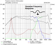
Here's something interesting about series filters. They align phase very well, but I talked about sacrificing flat frequency response. Whenever I do these things, I end up with a gaussian ripple on the frequency response, here a third order series filter. It's a feature! Quite pretty really. It's in the impedance too. Sorry about my poor drawing skills.
I could add that series filters have a flatter power response than parallel, which was one of Bud Fried's notions that I agree with.
Attachments
Last edited:
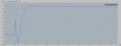
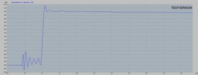
The first picture shows the measured step response of an asymmetric active crossover with low group delay. The second picture shows the same crossover fed via a group-delay equaliser made from 2nd order allpass filters. There is cleary some pre-ringing to be seen which happens at higher frequencies.
What happens when this is applied to a small coaxial speaker (together with some amplitude EQing) is shown in the third picture: A very nice step response.
Regards
Charles
What happens when this is applied to a small coaxial speaker (together with some amplitude EQing) is shown in the third picture: A very nice step response.
Regards
Charles
Attachments
Last edited:
The step-response is inverted. But who cares ? I was just too lazy to loosen and re-tighten eight screws. The picture would look nicer of course but it would be basically the same.
Regards
Charles
Regards
Charles
I suppose that is equalising the time delay between the main cone and the whizzer in effect.
I remember having a look ar Zaph's ZD5 filter, which includes a second order allpass network in the 2nd order tweeter filter to fix the time alignment. B&W did something similar in one of their models. Very few people would even understand what it does.
It sure looks impressive, until you try a 4th order tweeter filter. It does exactly the same thing!
I am determined not to drive myself crazy with these things. There always is a flaw, just like the old perpetual motion machines. 😀
Btw, isn't good transient response easy nowadays as FIR is cheap. A MiniSHARC / OpenDRC with a 2x2 plugin has enough taps to phase correct a LR4 down at 25 hz in addition to everything above.
Technically you are absolutely right but from an engineer's point of view it is unsexy ! 😉
Regards
Charles
Edit: And if you don't take care with FIR the cure might be worse than the desease ( => off-axis pre-ringing)
Regards
Charles
Edit: And if you don't take care with FIR the cure might be worse than the desease ( => off-axis pre-ringing)
Technically you are absolutely right but from an engineer's point of view it is unsexy ! 😉
Regards
Charles
Edit: And if you don't take care with FIR the cure might be worse than the desease ( => off-axis pre-ringing)
I rather think it is beautiful how simple it is 😀
But yeah, just because you can go crazy with FIR doesn't mean it's a good idea... but if you use it moderately, with shallow slopes of up to 24 dB then pre-ringing shouldn't be an issue.
I often think you reach a certain point in a thread where a review is necessary. 🙂
Transient perfect in real time is probably best approximated with fullrange headphones. Why not use the best?
I used to have these Koss electrostatic babies. Strangely they had a slightly weird sound, clear but uninvolving. Perhaps recordings aren't optimised for them because acoustic is important with live music.
Speakers are for sharing the fun with everybody. 😀
*We can optimise for flat frequency response with LR4 filters, but a dip in power response at crossover.
*Good phase with series filters, but ropey frequency response.
*Good time transients, but slow rolloff, which makes for distortion. Think Gaussian filters.
It seems like you always make one thing better and something else worse. 😕
Now with digital techniques we can fix the phase and time delay, so now we are left with the different dispersion of the two drivers which will abruptly change with a steep crossover.
See, I wonder if just the very act of splitting a signal into two parts is doing a quantum mechanical observation of which path the electron from the amp is going down? You partially collapses the ideal diffraction pattern.
So it all might be insoluble! 😱
Transient perfect in real time is probably best approximated with fullrange headphones. Why not use the best?
An externally hosted image should be here but it was not working when we last tested it.
I used to have these Koss electrostatic babies. Strangely they had a slightly weird sound, clear but uninvolving. Perhaps recordings aren't optimised for them because acoustic is important with live music.
Speakers are for sharing the fun with everybody. 😀
*We can optimise for flat frequency response with LR4 filters, but a dip in power response at crossover.
*Good phase with series filters, but ropey frequency response.
*Good time transients, but slow rolloff, which makes for distortion. Think Gaussian filters.
It seems like you always make one thing better and something else worse. 😕
Now with digital techniques we can fix the phase and time delay, so now we are left with the different dispersion of the two drivers which will abruptly change with a steep crossover.
See, I wonder if just the very act of splitting a signal into two parts is doing a quantum mechanical observation of which path the electron from the amp is going down? You partially collapses the ideal diffraction pattern.
An externally hosted image should be here but it was not working when we last tested it.
So it all might be insoluble! 😱
I have been largely able to ameliorate LF group delay issues in my xover applications using out of band elliptical notches by offsetting the HF drive center (which when horn loaded, is sometimes necessary anyway) backwards to match the LF overall delay, and also trading off the xover LF decreasing group delay at the low end against the increasing woofer group delay when approaching system resonance.
The result isn't exactly that of a single point source and probably can't be - even at listening distance I can resolve the height difference in the HF output and LF output with the vertical acoustic centers about a foot from each other if I try to. However, with an xover point of just over 500hz and mild initial slopes, the response nulls are almost directly above and below the speaker at that frequency, which I figure should minimize floor and ceiling room interaction at the speaker location which is consistent with the concept of a mildly directional speaker application above a few hundred hz.
Using a HF horn (such as I used with an Altec 288G driver and with a JBL 2220A woofer - getting enough bass from it below 80hz in a BR system was a different challenge), it is possible to horizontally match the lateral dispersions of both drivers near xover, which, along with the vertical notches appear to minimize the audibly apparent discontinuities of both drivers near xover in a listening environment. Of course, this is a specific design using 'classic' professional drivers and comparable overall results wouldn't be expected from a system using a 6.5" woofer using such techniques.
Btw, I also tried running the Altec 288G with a straight first order xover and found that LF information was severely distorting its presentation above moderate listening levels, partly since I was crossing over at a pretty low frequency for the horn used with it. When I introduced the the notch at about 250 hz (using 2 additional components and scaling the first order capacitor value by about 20% resulting in over 30db xover attenuation below this frequency), this problem essentially became a nonfactor at any practical listening level with only a small change of HF in band presentation near the xover frequency.
I suspect that a lot of the enthusiasm for using narrowband transition/high order speaker xovers results from professionals trying to get the highest sound output possible out of a given system in public performances. Using drivers capable of 120db output or better, I don't see such an imperative and am willing to give up a few db of system dynamic range for better home listening near xover, as long as the drivers have sufficiently good intrinsic performance.
@ phase_accurate
Hi, Thanx for trying to help 🙂
I see the DL link, however, i only got the first page ? as shown in my screenie.
On Espacenet - Original document The Captcha verification just ends in an endless loop of resubmitting different characters 😡
GB2448940 = Wind turbine monitoring Intellectual Property Office - Patent document and information service (Ipsum) What ?
GB2448940A is listed as a Foreign Reference on here Arrangement to detect a high rotational-speed of a blade - Siemens Aktiengesellschaft but is not actually relevent !
Anyway, from Figure 3 i see a 2 x 2nd order HP & LP passive xovers with buffers. The inductors & capacitors in the HP circuit are incorrectly transposed 😀 Obviously i havn't seen/read the full patent, due to the above issues, but i don't see anything Novel etc about their circuit in there ?
Hi, Thanx for trying to help 🙂
At the upper right you can choose to see the download links for the documents belonging to that case. The one that shows the whole patent document is called the "Publication Document"
I see the DL link, however, i only got the first page ? as shown in my screenie.
On Espacenet - Original document The Captcha verification just ends in an endless loop of resubmitting different characters 😡
GB2448940 = Wind turbine monitoring Intellectual Property Office - Patent document and information service (Ipsum) What ?
GB2448940A is listed as a Foreign Reference on here Arrangement to detect a high rotational-speed of a blade - Siemens Aktiengesellschaft but is not actually relevent !
Anyway, from Figure 3 i see a 2 x 2nd order HP & LP passive xovers with buffers. The inductors & capacitors in the HP circuit are incorrectly transposed 😀 Obviously i havn't seen/read the full patent, due to the above issues, but i don't see anything Novel etc about their circuit in there ?
Attachments

EDIT
Just realised i said "from Figure 3 i see a 2 x 2nd order HP & LP passive xovers" which of course should be, from Figure 3 i see a 2 x 3rd order HP & LP passive xovers !
Just realised i said "from Figure 3 i see a 2 x 2nd order HP & LP passive xovers" which of course should be, from Figure 3 i see a 2 x 3rd order HP & LP passive xovers !
The major fault is the use of negative resistors in the filters. From the frequency response point-of-view this actually works and you end up with phase responses that are mirror images of what the same type of filter usually is. You can even do this with SPICE etc.
If you want to try that it is sufficient to put a minus symbol in front of a resistor's value. I.e. you don't have to resort to INICs and the like for just a simulation. The problem with such filters is that they are not stable in the real world. SPICE again shows that when you try a transient response simulation. The voltages and currents go through the roof quite quickly.
Therefore it is always good to try a transient simulation also after developing/discovering some magic circuit.
Regards
Charles
Edit: It is patent nuber GB2489440 and not GB2448940 !
Last edited:
Ah, Charles, you've spotted the thing I missed. The negative resistance in the first section! 
This is a negative impedance converter: Negative impedance converter - Wikipedia, the free encyclopedia
It's not necessarily unstable, but it won't work the way he thinks. The source must have a significant impedance for stability, then the first "Lowpass" section produces a rising response, not a falling one with frequency. It's a group delay equaliser just like I described earlier. Trouble is that it largely cancels out the lowpass filter slopes in the second section too. So the two cascaded filters essentially do nothing. It's no sort of filter at all! 😀
Charles is right. It's not the NICs per se, it is the (uncompensated) poles in the right-hand s-plane in the overall transfer function that are the problem. It matters not how they are generated, an unstable filter is the inevitable result.
Steady-state frequency response simulation can indeed indicate both a linear and minimum phase response for arbitarily high filter orders. For those who prefer the theory, a proper factorisation of the transfer function will reveal the offending poles in the right-hand s-plane. For those who prefer the real world, building the circuit (or even simulating the (true) time-domain behaviour) will soon reveal the instability.
Right-hand s-plane poles imply a time-domain response that decays backwards in time (and hence grows in normal time). The best we can hope for when filtering in real-time (in theory) is to apply an overall delay to accommodate a trunctated version of the response required to extend into "negative time".
Unfortunately in the real-world, not only might such delays be an issue (at lower frequencies at least) but, as already stated in this thread, incomplete off-axis cancellation from crossover filters will produce "pre-echoes" that may well be more audible than the effects the delay-derived linear phase filtering is seeking to circumvent.
For a seminal review of the subject, I heartily recommend the set of AES papers by Stanley Lipschitz and John Vanderkooy on crossovers (or indeed on any of the subjects about which they profess!). I suggest these publications might be a good starting point for anyone wanting to play on a simulator...
Last edited:
Just a bit of clarification as to how such errors are made (by the operators of the simulators and not by the simulator software itself)...
A frequency response specified in magnitude and phase components (or equivalent) is termed "steady state" analysis. By steady state we mean picturing a snap shot in time, but also a snap shot that is assumed to have been unchanged for all time past and to remain as so for all time to come. Such analysis takes no account therefore of how a particular snapshot came to be or what will happen next.
In the real world, our snapshot will have come about causally and will therefore have a history. However, we can also imagine a world where exactly the same snapshot has apparently appeared from the future - the resulting magnitude and phase information give no clue as to which world our snapshot has come (though we know what the simulation does not).
A crossover filter (in part or in whole) can similarly be specified as a steady state construction with its time response being real (in normal time) or unreal (in "negative time") - or indeed a suitable combinaton thereof. We are left to decide what the steady state design procedure tells us.
And any filter that arrives at its steady state response before the input has been applied is one that exists in negative time and is therefore unreal (and unrealisable without the delay described above). Luckily we need not go to the effort of simulating the time domain response as we need only look at the positions of the poles in the s-plane: Any (uncompensated) poles in the right-hand s-plane are the ones that lead to instability and disappointment.
The crossover specified in the Patent Application has a transfer function with poles in the right-hand side of the s-plane. That is what the "novel" phase conjugation has achieved. The crossover is therefore unrealisable as a stable entity.
Which is a roundabout way of saying Charles had it nailed in his first post...
- Status
- Not open for further replies.
- Home
- Loudspeakers
- Multi-Way
- If transient-perfect only were that easy