not sure what your message here is ...
if you are suggesting that cascodes or current mirrors should be avoided for sonic reasons, this seems inconsistent with what i hear when listening to products from companies like Ayre, for example.
mlloyd1
if you are suggesting that cascodes or current mirrors should be avoided for sonic reasons, this seems inconsistent with what i hear when listening to products from companies like Ayre, for example.
mlloyd1
Just what I have expected from this thread.
Any cascode or current mirror has the leakage and "eat" the sound from the signal. That's what I am telling the OS and other guys here for years now. If you loose micro signals information from the input signal, you lose it and if it's not there no sim will tell you that, simply because sim is working in just an opposite way, looking what is happening with large signals and their harmonics. The only relevant test would be harmonically very complex low level input signal structure and its perfect copy on the output. Some kind of software should perform this test as a simulation or a measurement. Until then your only relevant test bench is your ears and what's between them.
The more you go complex the more you wash the sound, examples: Halcro, Soulution, etc.
Lazy Cat,
If I think I am following you here on your leakage comment let me see if I can put that into words. Are you saying that any parasitic leakage we could see in perhaps some voltage leaking between the base of a transistor and the emitter or collector is what you are talking about losing some of the signal, a very small voltage or current leak rather than a hard closed circuit where the energy is going somewhere it shouldn't be seen, something that we assume is off but allows a tiny portion to escape into the circuit where it doesn't belong? I would imagine that there are many of these so called parasitic leaks in any circuit, small loops through induction or capacitance that smear the signal so to speak. Isn't this the function of the NFB circuit and servo circuits to correct these errors whether with global feedback or local loop feedback correction?
If I think I am following you here on your leakage comment let me see if I can put that into words. Are you saying that any parasitic leakage we could see in perhaps some voltage leaking between the base of a transistor and the emitter or collector is what you are talking about losing some of the signal, a very small voltage or current leak rather than a hard closed circuit where the energy is going somewhere it shouldn't be seen, something that we assume is off but allows a tiny portion to escape into the circuit where it doesn't belong? I would imagine that there are many of these so called parasitic leaks in any circuit, small loops through induction or capacitance that smear the signal so to speak. Isn't this the function of the NFB circuit and servo circuits to correct these errors whether with global feedback or local loop feedback correction?
Any impedance disorder in the signal path, via current leakage to GND or in between the stages. The result is big difference in uV region, losing micro signals in audio signal.
Tested many amps in ABX test, the same sch only one difference between the two. At the end simpler always sounded better. Of course not too simple.
This is correct only if the impedance you mention is strongly frequency-dependent.
A well-designed wide-bandwidth amplifier will react on any input signal above the noise level, reproducing it at the output. It will not be lost. Any input uV above the noise will be visible at the output. It may be distorted because of non-linearity, low slew-rate, phase/frequency dependence, etc., but it will be there.
Also, Kindhornman is absolutely right about the role of NFB(s) here - they will improve the situation. If something will be lost, neither current mirrors, nor cascodes will be the reason.
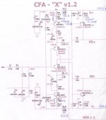
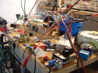
I couldn't resist the temptation to assemble this CFA-X V1.2.!
More details tomorrow.....
From a very first test this singing very well!!!
All small signal transistors TCSA970 ,C1845 NOT GOOD MATCHED(970 hfe=200,c1845hfe=290)
More details tomorrow.....
From a very first test this singing very well!!!
All small signal transistors TCSA970 ,C1845 NOT GOOD MATCHED(970 hfe=200,c1845hfe=290)
Attachments
Last edited:
Hi Terry, I would suggest you to use the same sch as Jason did in post #1708 or the one from #1744 😉
Hi Lazy Cat ,i agree!Hi Terry, I would suggest you to use the same sch as Jason did in post #1708 or the one from #1744 😉
Isn't this the function of the NFB circuit and servo circuits to correct these errors whether with global feedback or local loop feedback correction?
Yes, but each feedback loop has its inherent summarized error, depending on loop gain, bandwidth, subtraction modulation error, etc. No matter the input stage, whether LTP or CFI is capable of, it cannot force the rest of the circuit to exactly follow the correction signal because it is just too complex and demanding, normally exceeding the performance limits of other parts of the circuit. All in all the whole sch parts are responsible for overall global negative feedback loop performance not just the input stage. In that context every little detail of the sch matters and participating in correct or wrong way, that is why the amps are different as day and night.
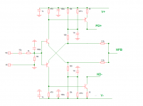
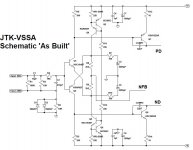
I don't see a schematic in #1708. #1744 is more than I want to attempt on a veraboard. I suppose Jason might have more boards. Am I correct that it would look like the attached?
Yup, like that. I have a small stack of boards still Terry, contact me if you want some spares to experiment with. No schematic in 1708, just a pic showing what I did with the partially stuffed board.
I couldn't resist the temptation to assemble this CFA-X V1.2.!
More details tomorrow.....
From a very first test this singing very well!!!
All small signal transistors TCSA970 ,C1845 NOT GOOD MATCHED(970 hfe=200,c1845hfe=290)
After that, you can do some experiment to increase the slew rate. Change R8 and R9 to 1K or 1K1 (2K2 || 2K2), R7 and R10 to 33 (I think not necessary to use 2Watt resistor here). You may change value of CCS to get VAS current in the range 4,5 - 5 mA.
Change R15 and R18 to 100 Ohm to reduce THD a bit.
One of the things I would like to try are some relatively 'basic' circuits to try to hear the merits of a specific topology. My thoughts are if they are developed to the same level of technical excellence then they may well sound the same, or at least more similar than they otherwise might.
Pitting a relatively basic plain vanilla VFA like a Linn against a relatively simple CFA like a VSSA should showcase the differences. If every measurable parameter is developed to be equal between the camps then there may well end up being no discernible difference.
At any rate, I'm going to assemble a pair of monsters and test first with the VSSA front end to see how it sounds against the Lateral MOSFET VSSA. Then I'll turn my attention to some of the IPSs OS has presented. A Spooky Leach re-draw has been started.
Lazy Cat,
I agree on a micro scale level it is always better to get things as accurate as possible so any correction needed in minimized. This to me is no different than someone who does mathematical calculations and does not round off any values until the final calculation is made compared to the person that rounds at every opportunity and gets less accurate results in the end, the rounding errors can and do add up and I would think the same would be true with electrical audio circuits. I will just have to learn the procedure to match components to the best ability I can when the time comes for that, why wouldn't you do that if you can? That doesn't mean that I don't believe in negative feedback but why not let it do the least amount of work or demand the least out of that part of the circuit. I think this way in my speaker designs so why not on the electronic side. I don't ignore things like the sound contribution of the surround material on a dynamic driver, it is the sum of all parts working together that gives the final results.
I agree on a micro scale level it is always better to get things as accurate as possible so any correction needed in minimized. This to me is no different than someone who does mathematical calculations and does not round off any values until the final calculation is made compared to the person that rounds at every opportunity and gets less accurate results in the end, the rounding errors can and do add up and I would think the same would be true with electrical audio circuits. I will just have to learn the procedure to match components to the best ability I can when the time comes for that, why wouldn't you do that if you can? That doesn't mean that I don't believe in negative feedback but why not let it do the least amount of work or demand the least out of that part of the circuit. I think this way in my speaker designs so why not on the electronic side. I don't ignore things like the sound contribution of the surround material on a dynamic driver, it is the sum of all parts working together that gives the final results.
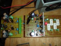
some photos from this CFA-X V1.2
Attachments
Last edited:
Hi bimo i will try all these modifications soon.🙂After that, you can do some experiment to increase the slew rate. Change R8 and R9 to 1K or 1K1 (2K2 || 2K2), R7 and R10 to 33 (I think not necessary to use 2Watt resistor here). You may change value of CCS to get VAS current in the range 4,5 - 5 mA.
Change R15 and R18 to 100 Ohm to reduce THD a bit.
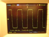
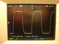
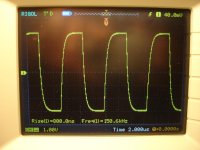
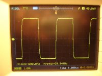
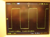
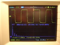
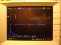
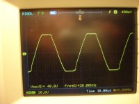
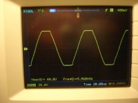
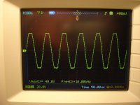
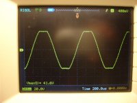
Now the test process
Attachments
-
 16res.JPG150.6 KB · Views: 155
 -
 17res.JPG166.9 KB · Views: 145
 -
 18res.JPG163.3 KB · Views: 181
 -
 19res.JPG167 KB · Views: 206
 -
 15res.JPG172 KB · Views: 170
 -
 14res.JPG176.9 KB · Views: 164
 -
 13res.JPG188 KB · Views: 149
 -
 12res.JPG196 KB · Views: 544
 -
 11res.JPG167 KB · Views: 564
 -
 10res.JPG152.2 KB · Views: 599


😡
its only 20V P-P.
Look thimios how 200 kHz square waves under load should look from good CFA. You still have to do some work on this design hehe
its only 20V P-P.
😡
its only 20V P-P.
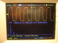
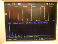
on 4 Ohm load 😉
thimios has 6 Vpp at 150 kHz 🙄
Show me your's amp 200 kHz at 20 Vpp square wave under 4 Ohm load 😎
- Home
- Amplifiers
- Solid State
- Slewmaster - CFA vs. VFA "Rumble"