Dear All,
I am planning to build a ported subwoofer with the Dayton Audio SD270A-88 DVC driver. The sub would be powered by a 200W class AB plate amp. The sub will be tuned to 30Hz in a 60 ltr box with vent dia 7cm and length 16 cm. It will be used as a supplement to floor standing speakers of Fb of around 45 Hz. I am attaching h/w the simulation using unibox. Is the tuning frequency and box volume correct? Or should I tune it lower with a bigger box ? Will it be suitable for home use? pl give Your comments on transient response also.
regards
Prashant
Attachments
Dayton Audio SD270A-88 10" DVC Subwoofer
Dual 8 ohm voice coils connected in parallel (T/S parameters.)
Power Handling (RMS) 80 Watts
#1. A standard application (read ideal) would be a reflex with:
VB = 112 L, tuned to FB = 19 Hz
(port: ~9.5/42.5 cm)
#2. Now a sono/PA application with reduced volume would be:
VB = 100 L, FB = 25.5 Hz
(port: ~12/42 cm)
#3. A sub/speaker with 60L (net) and lower tuning:
VB = 60.0 L, FB = 25.4 Hz
(2x ports: ~7.5/60 cm)
#4. A sub/speaker with 60L (net) and high tuning 30Hz (yours/not correct):
VB = 60.0 L, FB = 30.0 Hz
(3x ports: ~7.5/65.5 cm)
It shows that your calculation for the port is right but you did forget about the air speed that is about (more that it should) 44.4 m/s, KL = 0.088. You need 3 ports. The air speed should be inferior to 14.8 m/s.
If possible use the lower tuning like in #3.
Take into account in the total volume (net):
Displacement of 10" driver (10 inch - 1.5 liters)
2 Ports (like in #3) 2x 3 liters - each = 6 liters
Total: 7.5 liters (out of 60L) 52.5 L net? - note: I would say that is not enough. 🤐
Hi Inductor,
Thanks for the reply. In simulation I did with your suggestions, I see following
case 1: VB = 112 L, tuned to FB = 19 Hz (port: ~9.5/42.5 cm) .
Peak cone excursion exceeded, port air velocity high.
Case 2:VB = 100 L, FB = 25.5 Hz (port: ~12/42 cm)
Peak cone excursion high.
case 3: VB = 60.0 L, FB = 25.4 Hz (2x ports: ~7.5/60 cm)
Port resonance high
Case4: VB = 60.0 L, FB = 30.0 Hz (3x ports: ~7.5/65.5 cm)
Port resonance high.
Am I doing something wrong here or what?
reg,
prasi
Attachments
Hi Inductor,
I will not be playing it at very high volume as I live in an apartment. Supposing I play at 30W level, the port air speed will be less. In this case will it work?
reg
prasi
I will not be playing it at very high volume as I live in an apartment. Supposing I play at 30W level, the port air speed will be less. In this case will it work?
reg
prasi
Last edited:
I don't know what you are doing, in my case (case#1) and should be the same for you, if using a reflex enclosure for Dayton Audio SD270A-88 DVC, VB = 112.6 L and FB = 19.3 Hz - using (RMS) power ~70 W@4 Ohms (V=16.02 V) we have 6 mm. The speaker is 80 W (RMS) from spec. Port air velocity is now 11.3 m/s, KL = 0.150 lower than 15.0 m/s. 😀
Your picture #1 shows excursion at levels of ~11 mm ??? What power you're using?! 🙂
If you use only 30 W better to model that in the software and see (WinISD, other). 😉 That's about half lower than spec and your speaker doesn't need to be so extreme so to speak, ports, excursion. What is the frequency of the crossover and what is your set-up or other equipment you are using besides the amp for the sub, just for me (and others) to get the idea.
In the model case#3 what do you mean by:
Resonance of the port is 288 Hz.
If that's what you are saying. 😕 😎
Your picture #1 shows excursion at levels of ~11 mm ??? What power you're using?! 🙂
If you use only 30 W better to model that in the software and see (WinISD, other). 😉 That's about half lower than spec and your speaker doesn't need to be so extreme so to speak, ports, excursion. What is the frequency of the crossover and what is your set-up or other equipment you are using besides the amp for the sub, just for me (and others) to get the idea.
In the model case#3 what do you mean by:
Port resonance high
Resonance of the port is 288 Hz.
If that's what you are saying. 😕 😎
Attachments
Hi Inducor,
Regarding the set-up, I have following
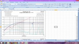
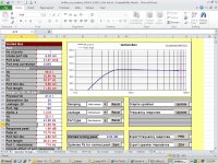
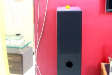
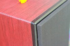
1. A pair of DIY floorsanders driven by a 25 W per channel stereo amp. This amplifier has an line out which will be used as a low level input to the subwoofer plate amplifier. The Floorstanders are tuned to 42Hz and its simulation is attached herewith, along with photographs of the speaker.
Regarding the set-up, I have following
1. A pair of DIY floorsanders driven by a 25 W per channel stereo amp. This amplifier has an line out which will be used as a low level input to the subwoofer plate amplifier. The Floorstanders are tuned to 42Hz and its simulation is attached herewith, along with photographs of the speaker.
Attachments
Regarding the sub plate amp,
The specs are as follows
1: power - 200 watt RMS
2: THD - less than 0.05% at rated power
3: frequency response : 20 Hz - 150 Hz
4: filter : 24 db butterworth continuesly variable form 40 hz to 150 Hz
The specs are as follows
1: power - 200 watt RMS
2: THD - less than 0.05% at rated power
3: frequency response : 20 Hz - 150 Hz
4: filter : 24 db butterworth continuesly variable form 40 hz to 150 Hz
If you use only 30 W better to model that in the software and see (WinISD, other). 😉 That's about half lower than spec and your speaker doesn't need to be so extreme so to speak, ports, excursion. What is the frequency of the crossover and what is your set-up or other equipment you are using besides the amp for the sub, just for me (and others) to get the idea.
In the model case#3 what do you mean by:
Resonance of the port is 288 Hz.
If that's what you are saying. 😕 😎
Dear Inductor,
the meaning of port resonance high is the secondary outputs from the port at higher frequencies. My mistake, at those frequencies, the amp filter would be crossed at 70-80 Hz so the port resonance is not an issue for subwoofers.
I don't know what you are doing, in my case (case#1) and should be the same for you, if using a reflex enclosure for Dayton Audio SD270A-88 DVC, VB = 112.6 L and FB = 19.3 Hz - using (RMS) power ~70 W@4 Ohms (V=16.02 V) we have 6 mm. The speaker is 80 W (RMS) from spec. Port air velocity is now 11.3 m/s, KL = 0.150 lower than 15.0 m/s. 😀
Your picture #1 shows excursion at levels of ~11 mm ??? What power you're using?! 🙂
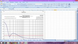
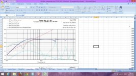
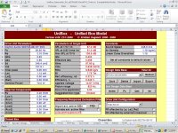
I am using Unibox for my simulation. Here are the inputs and simulated results. I have rechecked all inputs regarding T/S parameters, power, etc and everything is correct. but why is the difference? 😕
Attachments

prasi,
Ok, what I can find for now, after looking at the 2 softwares, mine and yours, and comparing.
1. Besides small details in climate/temperature and Q for the port (that are almost the same) and that we can change in both softwares, air speed (345.0 m/s) being the same in both and my air density being almost 1.19 Kg/m3, for a temperature of 20ºC and 50m above sea level. After matching the constants and port (x3) "variables Q", I proceeded with a fair comparison: 😀
2. You have 7 graphics with measurements and T/S parameters data, for in your post above for driver Dayton Audio SD270A-88 DVC in software UniBox.
3. I'm using the software from Petoin Dominique (FR). I checked for all the parameters and they come very close to each other in results sometimes in the +1/-1 decimal position. The way (all) the softwares input the results for each driver (T/S parameters), checking for their consistences, have some variances that do not affect the results in a "grand scale" so to speak like in this case. Both you and me have very close parameters input, in the software for the driver and enclosure, having then very close results out.
4. Comparing the real results of the data output:
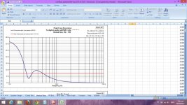
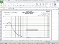
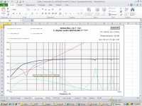
Going to your last picture #7.
In your picture, it shows that DRIVER with a vented box 112L@19Hz and port 10/42 cm, 70W (RMS) has an air speed 22 m/s. (Your picture above #2 shows another port 9.5/42 cm).
In my case for the driver in the same conditions (same tuning/~port/~RMS) 112L@19Hz, port 9.4/44.7 cm, ~72W (RMS) gives an air speed: 11.0 m/s.
For me the only explanation I can find is that my software in counting upfront with thermal compression or thermal attenuation that is in this case of ~2dB's.
So, for a max SPL* 106.2 dB and after thermal compression, we end-up with 104.2 dB, having some effect on the air speed, being it lower (in my case). That is the only explanation I can find. 🙂
Try reducing your "SPL" by the same amount and check back the air speed.
*) The same or similar to yours, mine is (1m) 106.2 dB for ~72W and yours 105.9 dB for 70W.
Answer: Not that important, if using only 30W (RMS).
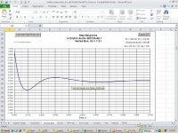
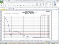
Going to the above picture #4 (driver excursion).
It shows DRIVER in vented box 112L@19Hz but Xmax at 7mm (red line), why?
Here the excursion (in your picture) that the driver is showing is of 10.5 mm@30Hz.
Again, I don't have explanation for that fact besides a possibility of thermal attenuation and max. final SPL. My software is showing different data (because) 6.0 mm@30Hz is the condition of max power/voltage from the amplifier.
Answer: Different results for max SPL accepted by the DRIVER, as an imput and different end results after thermal attenuation. Not problematic if you are using 30W (RMS). I believe that, after calibrating the same enclosure for the same DRIVER and after matching the same power/SPL that results will be very close to each other. Maybe ports will have a difference of +/- 1 cm as was stated already.
This was the best I could come up with, with the time available. I don't find a necessity to take it further. Besides that, using the enclosure that best suites you (60L) and the alignment/tuning that you prefer, I think yours has little high tuning. I can not understand why, besides having a one-note speaker "in extremes" and making more noise (having a shorter port was another reason). That's why I said a lower tuning, 25Hz instead of 30Hz, like in project #3 from post#2, would be beneficial. 😀
Ok, what I can find for now, after looking at the 2 softwares, mine and yours, and comparing.
1. Besides small details in climate/temperature and Q for the port (that are almost the same) and that we can change in both softwares, air speed (345.0 m/s) being the same in both and my air density being almost 1.19 Kg/m3, for a temperature of 20ºC and 50m above sea level. After matching the constants and port (x3) "variables Q", I proceeded with a fair comparison: 😀
2. You have 7 graphics with measurements and T/S parameters data, for in your post above for driver Dayton Audio SD270A-88 DVC in software UniBox.
3. I'm using the software from Petoin Dominique (FR). I checked for all the parameters and they come very close to each other in results sometimes in the +1/-1 decimal position. The way (all) the softwares input the results for each driver (T/S parameters), checking for their consistences, have some variances that do not affect the results in a "grand scale" so to speak like in this case. Both you and me have very close parameters input, in the software for the driver and enclosure, having then very close results out.
4. Comparing the real results of the data output:
Going to your last picture #7.
In your picture, it shows that DRIVER with a vented box 112L@19Hz and port 10/42 cm, 70W (RMS) has an air speed 22 m/s. (Your picture above #2 shows another port 9.5/42 cm).
In my case for the driver in the same conditions (same tuning/~port/~RMS) 112L@19Hz, port 9.4/44.7 cm, ~72W (RMS) gives an air speed: 11.0 m/s.
For me the only explanation I can find is that my software in counting upfront with thermal compression or thermal attenuation that is in this case of ~2dB's.
So, for a max SPL* 106.2 dB and after thermal compression, we end-up with 104.2 dB, having some effect on the air speed, being it lower (in my case). That is the only explanation I can find. 🙂
Try reducing your "SPL" by the same amount and check back the air speed.
*) The same or similar to yours, mine is (1m) 106.2 dB for ~72W and yours 105.9 dB for 70W.
Answer: Not that important, if using only 30W (RMS).
Going to the above picture #4 (driver excursion).
It shows DRIVER in vented box 112L@19Hz but Xmax at 7mm (red line), why?
Here the excursion (in your picture) that the driver is showing is of 10.5 mm@30Hz.
Again, I don't have explanation for that fact besides a possibility of thermal attenuation and max. final SPL. My software is showing different data (because) 6.0 mm@30Hz is the condition of max power/voltage from the amplifier.
Answer: Different results for max SPL accepted by the DRIVER, as an imput and different end results after thermal attenuation. Not problematic if you are using 30W (RMS). I believe that, after calibrating the same enclosure for the same DRIVER and after matching the same power/SPL that results will be very close to each other. Maybe ports will have a difference of +/- 1 cm as was stated already.
This was the best I could come up with, with the time available. I don't find a necessity to take it further. Besides that, using the enclosure that best suites you (60L) and the alignment/tuning that you prefer, I think yours has little high tuning. I can not understand why, besides having a one-note speaker "in extremes" and making more noise (having a shorter port was another reason). That's why I said a lower tuning, 25Hz instead of 30Hz, like in project #3 from post#2, would be beneficial. 😀
Hi Inductor,
Thanks for the detailed explanation. I will go ahead with your suggestion of lower tuning (25Hz). Could you kindly elaborate on "besides having a one-note speaker in extremes"?
Regarding the driver,
Although I know there are much better drivers available, I am going ahead with this dayton audio driver only because of budget constraints. I would like to get my hands on one of the Morel drivers like Morel UW1258 Ultimate 12" Subwoofer. Alas! I cant🙁.
Could you suggest me, a proper tuning freq and driver parameters for the home use with my current set-up?. I will then try to find out drivers available in India closely matching your suggestions.
thanks and regards
prasi
A high Q or peak gives you an accent (musical sound) in one frequency only. That is useful when matching/designing speakers 2-way and 3-way to give a flat response in frequency what is not the case. Is also useful if the output had a dip or attenuation @the same frequency what is not the case. It might make the frequency response uneven and awkward if used hard, your has a ~2dB's peak that I would consider the/your limit in this case. That and room gain might create a lot of problems only visible with room simulation software. 😎"besides having a one-note speaker in extremes"?
Dear Inductor,
based on the suggestions given by you and other considerations (I will be playing the sub at < 30-40W power all the time), I have re-designed and re-simulated the vented sub enclosure. The driver is same i.e., Dayton Audio DA-270-88 DVC sub. The new design has following specs.
Applied Power RMS: 40 W
Net Vol of enclosure: 102.7 ltrs
Fb: 23 Hz
F3: 24.21 Hz
No of ports:2
Inside port dia.:6.99cm
Port end correction:0.732
Port length:35.04 cm
Port Air Velocity : 16m/s
I have attached the pdf of the unibox simulations. Kindly go through the pdf and suggest any improvements. Also kindly give your specific comments about the step response/transient response, whether the box will sound boomy or is it acceptable.
Since you the expert in diy audio field , and I am only a beginner, I hope you will help me as you did before. I also would like invite other experts to help me in this project.
regards
prasi
Attachments
102.7L@23Hz (or lower) for Dayton Audio SD270A-88 DVC
Your calculations are very fine, close to mine. Check/test ports on site with the real speaker/sub for the best lengths/tuning 36 cm on my simulation (with shorter port tuning goes up in frequency and so goes the bump in dB). You may try a longer port, to 44 cm with lower tuning (@21Hz) as an experience. Don't abuse of the internal insulation or you will end with a muffled sound or a "sealed type alignment" that works great for a sealed enclosure. As an added bonus, make ~12/13 cm the distance between the centers of ports. Air speed is lower than 14.7 m/s.
Your calculations are very fine, close to mine. Check/test ports on site with the real speaker/sub for the best lengths/tuning 36 cm on my simulation (with shorter port tuning goes up in frequency and so goes the bump in dB). You may try a longer port, to 44 cm with lower tuning (@21Hz) as an experience. Don't abuse of the internal insulation or you will end with a muffled sound or a "sealed type alignment" that works great for a sealed enclosure. As an added bonus, make ~12/13 cm the distance between the centers of ports. Air speed is lower than 14.7 m/s.
Hi Inductor,
Thanks for the reply. I will definately try with different port lengths to see which one gives best bass. For the internal insulation, the walls will covered with just one layer of 6mm thick felt material and 1/2 pound of polyfill on the internal wall of rear baffle.
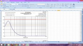
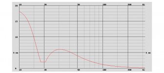
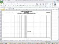
Also any comments about the step response (on page 6 of attachment of Post # 13) ?
I am attaching herewith the preliminary drawing of the sub. There will be a central bracing plate (details given in drawing) and Also triangular battons on all corners to strengthen the cabinet. The design is similar to Seas L26ROY sub woofer kit (http://www.madisound.com/loudspeaker_specifications/L26ROY_SUBKIT_PORT.pdf) offered by madisound but with larger volume.
regards
prasi
Thanks for the reply. I will definately try with different port lengths to see which one gives best bass. For the internal insulation, the walls will covered with just one layer of 6mm thick felt material and 1/2 pound of polyfill on the internal wall of rear baffle.
Also any comments about the step response (on page 6 of attachment of Post # 13) ?
I am attaching herewith the preliminary drawing of the sub. There will be a central bracing plate (details given in drawing) and Also triangular battons on all corners to strengthen the cabinet. The design is similar to Seas L26ROY sub woofer kit (http://www.madisound.com/loudspeaker_specifications/L26ROY_SUBKIT_PORT.pdf) offered by madisound but with larger volume.
regards
prasi
Attachments
Hi Inductor ,
Sure Iwill try to be more clear.
Here is my earlier post (Post no 15#, edited for clarity).
"
Question1: For the internal insulation, I am planning to cover the internal walls with just one layer of 6 mm thick felt material and 1/2 pound of polyfill on the wall behind the driver. Is this OK?
Question 2 (important): Do you have any specific comments about the step response (on page 6 of attachment of Post # 13) ? Will the subwoofer sound boomy? or will it give a tight, clean baas? I am attaching the step response fo more clarity.
Question 3: Now for the actual box design.
I am also attaching herewith the preliminary drawing of the sub. There will be a central bracing plate (details given in drawing) and Also triangular battons on all corners to strengthen the cabinet. The design is similar to Seas L26ROY sub woofer kit (http://www.madisound.com/loudspeaker_specifications/L26ROY_SUBKIT_PORT.pdf) offered by madisound but with larger volume. Is this design good enough?or do you suggest any changes ?
regards
prasi
Attachments
Last edited:
back view ?
Hi there: The back view on your drawing shows a 9.5"x8.9" square. What is that? ...regards,Michael
Hi there: The back view on your drawing shows a 9.5"x8.9" square. What is that? ...regards,Michael
Looking at the pdf that must be: ""#8. sub-plate amp cut out dims incorporated, to be confirmed from actual part""Hi there: The back view on your drawing shows a 9.5"x8.9" square. What is that? ...regards,Michael
- Status
- Not open for further replies.
- Home
- Loudspeakers
- Subwoofers
- Subwoofer with Dayton Audio SD270A-88 DVC