The bjt triple could be protected from oscillation with only base-colector cap on only driver transistor (VT7), why on all 3 bjts?
I used the russian KT947A, its base current transfer ratio is like this. I have found that more or less close substitute for them are MRF422.
The graph is far from good. Why have you chosen this transistor over lot more linear 2SC5200 or MJL3281??
The graph is far from good. Why have you chosen this transistor over lot more linear 2SC5200 or MJL3281??
Hello, Bogdan
I have already mentioned in the #5:
"...that very low Rout values give no warranty for correct bass sound (I judge with high quality recordings of double-bass, bass-guitar and big drums). Subjective bass depends on many aspects of definite amp - definite speaker interactions, one needs a kind of empirical adjustment. Some of my SE amps, which include output stage in the NFB loop, with Rout close to 0,01 Ohms, produce "less correct" bass. I've found, that a kind of non-linearity, given by VHF power bjt used (their "h21 vs collector current" curve is not flat, it does not drop at 3...5A, on contrary, it continues growing up to 25A), allows to improve amp-speaker interaction, most probably by better counter-action to speaker back-emf. Some people arrange some positive feed-back, adjusted to their speakers. In my case, with PMC EB1i speakers, just the "non-linearity" caused by rising h21 is just OK. One should also bear in mind, that GNFB is usually not a good cure for improving bass, it does change bass, but not necessarily in correct manner."
My experience says, that the linear region followed with fast drop down of h21 vs current at 3...4A is not good. For a good bass, output stage should produce definite type of non-linearity, that compensate imperfections of speakers (back-emf).
I have found this first with special Ge power transistors (1T910A) that have similar growing h21 curve. Output power transistors must "love current", be ready to give it more and more. On the contrary, lateral mosfets "afraid of current", theirfor one never get "beefy" bass with them, even if Zout is zero.
Last edited:
The bjt triple could be protected from oscillation with only base-colector cap on only driver transistor (VT7), why on all 3 bjts?
This is not true with VHF BJTs. Every transistor is to be protected independently, unfortunately. Trials and errors with them are very expensive. All of them are intentionally designed for easiest falling into oscillations. Internal resistance of the base region is very small. But, this gives benefits such as "love to current".
Last edited:
My gosh, have you seen the price of the MRF422 on eBay these days 😱
I'm afraid this will be a show-stopper for many, but there is much of importance to learn from you on this design approach.
The Russian KT947A costs $6.76 per piece in Moscow retail store...
Makes sense to buy from here 😉
Member
Joined 2009
Paid Member
HSome people arrange some positive feed-back, adjusted to their speakers.
very astute to note this, I believe it is a good solution if you can't find the output devices you specify.
Hello, Bogdan
I've found, that a kind of non-linearity, given by VHF power bjt used (their "h21 vs collector current" curve is not flat, it does not drop at 3...5A, on contrary, it continues growing up to 25A), allows to improve amp-speaker interaction, most probably by better counter-action to speaker back-emf.
Interesting and also strange observation. As I understand, the amp`s output impedance should change with the load for good sound?
Why VHF transistors then, when you "kill" their speed with compensation caps?
What`s the purpose of CCS with such low imedance?
So many questions... 🙂
Member
Joined 2009
Paid Member
As I understand, the amp`s output impedance should change with the load for good sound?
Perhaps this makes sense where very little feedback is used to cope with the non-linear load impedance ?
Actually a choke would probably work very well in the o/p in ur design Vladimir - did you ever try one. I think 5 - 10mH + 0.1R might be about right
Chokes work far more efficiently & effectively in low voltage / high current environments than they do in high voltage / low current environments.
Strange that they feature so much in tube designs and so little in solid state designs.
This isn't strange at all. Consider that hollow state is high voltage, low current. Even the beefiest of the vacuum power diodes, the 5U4GB, has an Isurge rating of 1.0A/plate. Using two in parallel would give you a 2.0A Isurge. That may seem like a lot, but it isn't really, not when compared to the Isurge of Si diodes.
Power supply filtering isn't a matter of sticking a huge amount of capacitance after the diode. Even going with 47uF exceeds the rating, and a 100uF reservoir capacitor would have a 5U4GB crying "Uncle!". Given that, you need another means to reduce the ripple, and that has traditionally meant an RLC LPF after the reservoir capacitor. (These days, you can substitute active decoupling, but that wasn't an option back in "the day", as transistors didn't exist, or if they did, there weren't any decent power transistors to implement it.)
In solid state designs, it's NBD to use some 30000uF of filtering capacitance to get that ripple down below 1.0Vp-p. You're not gonna get away with that in hollow state work. You can't do it if you're using vintage PTXs, or even modern versions such as the Hammond "Classic" line, as these were never designed with extreme Isurge in mind. Your Si diodes won't mind, but your PTX just might.
You also have to consider that low-L inductors that can handle the currents encountered in SS practice are gonna be big and heavy. They have to have large cores to stand up to the magnetization of currents considerably north of an amp.
Perhaps this makes sense where very little feedback is used to cope with the non-linear load impedance ?
I`m talking about output stage and , the output stage is not in the feedback loop.
Interesting and also strange observation. As I understand, the amp`s output impedance should change with the load for good sound?
Why VHF transistors then, when you "kill" their speed with compensation caps?
What`s the purpose of CCS with such low imedance?
Bogdan, your questions and doubts are absolutely correct, I did put them to myself also.
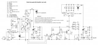
One can use any better CCS, but 100 Ohms actually not so bad, at 4A consumption, for the rail decoupling from passing output signal. Other CCSs can be better in R value, but be careful with their ability to handle fast transients (this is most important from my experience).
Strange VHF transistors provide several benefits. The first is rated power, 300W, that allows to avoid paralleling and vasting output impedance by emitter resistors. The second that not VHF 300W ones (MJ or BUV) are only few MHz, and their h21 drops down at 3-4A. The few MHz is not good for any feed-back applications. The third, voltage dependencies of inter-electrode capacitances of VHF transistors are much more flat than of low-frequency ones. Adding some high-quality external resistors and caps makes the flatness even better, almost perfect at working range.
About handling the back-emf, another solutions based on specific kinds of feed-back are possible, but for me is it better, then this job is done by the output device itself, without any loops. When we have many various loops in schematics, we must either kill the speed and get "dark" sound, or preserve some speed and get "bright, annoying" sound (IMO).
Last edited:
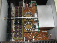
View inside the amp. The preliminary voltage amplification stage is sitting in its own cabinet, input RCA connectors go to inside of this cabinet. Power supply is external, 4-pin Speakon connectors are used for connecting the output stage supply voltage and the preamp voltage.
Attachments
You have mentioned that having caps in the output signal path does not present a problem with quality but you do seem to take o/p capacitors very seriously indeed - I never saw such a large array used in the signal path.
Can you describe the sonic benefit of having so many paralleled caps in the o/p path.
mike
Can you describe the sonic benefit of having so many paralleled caps in the o/p path.
mike
Last edited:
You have mentioned that having caps in the output signal path does not present a problem with quality but you do seem to take o/p capacitors very seriously indeed - I never saw such a large array used in the signal path.
Can you describe the sonic benefit of having so many paralleled caps in the o/p path. mike
Mike, this approach to output cap was taken as result of extensive experiments and listenings. I do know the axiom that "the best cap is no cap". Therefor I exclude participation of PS caps in output signal (by "rails decoupling") and almost in active schematics, except for output cap.
Actually, I have assembled and listened carefully to several SE balanced schematics (direct current amplifiers), also rails decoupled. Their sound is a reference for me, they are in all aspects better than a competently desinged and manufactured tube amp (SE 300B). But, their problem is output power. For a real-world speakers one usually wants at least 30W. And my PMC EB1i are more demanding than average. So, the output cap is a compromise, but, after comparison with references, I have found that this compromise is much less than, for instance, difference between volume pots (DACT and Alps RK27). This compromise is of order of difference between various RCA input connectors. So, better to have power and speakers protected.
Principle of assembling the output cap is a three-parts solution.
First part - polystyrene and polypropylene audiophile caps (1uF, 10uF, 47...100uF).
Second part - best quality small (around 1000uF) electrolytics (16...24pcs).
These two parts are the main contributors to sound quality.
Third part - regular quality big electrolytics (10000uF) just for supporting the very bottom end. Usually, just for excluding their contribution to mids and trebles, I separate them by putting 0,02 Ohms resistor befor them.
Such "output cap design" is a result of extensive listenings and comparisons. Please, do not believe those who support "good quality big electrolytic is enough".
With more than 100mF connected as the DC blocker on the output, how long do you wait for them to charge up, before connecting the speaker?
Do you have to disconnect the speaker to allow them to discharge on shutdown?
Do you have to disconnect the speaker to allow them to discharge on shutdown?
With more than 100mF connected as the DC blocker on the output, how long do you wait for them to charge up, before connecting the speaker?
Do you have to disconnect the speaker to allow them to discharge on shutdown?
Both switching On and Off are absolutely quiet (no sound) without any additional measures.
At power-On, supply voltages are rising smoothly during several seconds, according to time constants (10kOhms-100uF) at the voltage stabs.
At power-Off, their is no sound also, or very-very low level, almost unlistenable.
The 4A power supply, every channel, includes RCRC in the external block with around 100mF, and CRC in the main block (first C is mica || film for HF filtering, second C is 50mF). After goes the voltage stab.
Last edited:
Have you tried to add the rc snubbers for output coupling caps?
What about symmetrical rail voltages with no output cap? Offset problems or something else?
What about symmetrical rail voltages with no output cap? Offset problems or something else?
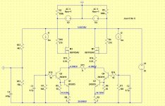
The elegance of the current flow in this design is lost if you go to bipolar supplies.
As Vladimir mentions the most elegant version is single rail & full balanced working.
I've been playing with Pavel's design in spice. This should work well with my balanced DAC 🙂
I think I will begin with this simple & cheap version and try Vladimir's ideas one at the time.
As Vladimir mentions the most elegant version is single rail & full balanced working.
I've been playing with Pavel's design in spice. This should work well with my balanced DAC 🙂
I think I will begin with this simple & cheap version and try Vladimir's ideas one at the time.
Attachments

- Status
- Not open for further replies.
- Home
- Amplifiers
- Solid State
- Rails Decoupled SE Amplifier