Member
Joined 2009
Paid Member
I`m talking about output stage and , the output stage is not in the feedback loop.
Exactly my point ! there's no feedback so that is why he cares about the way the output device characteristic responds to load impedance, if he had feedback then it would be the behaviour of the closed-loop amplifier that mattered instead.
Have you tried to add the rc snubbers for output coupling caps?
What about symmetrical rail voltages with no output cap? Offset problems or something else?
With the values of caps indicated above (film 1, 10, 56, lytics 1000, 10000) I am shure we do not have resonances and ringing. Typical conditions for parasitic ringing are - small mica cap in parallel to big (10000uF) lytic. At high frequencies the lytic acts as L, and we come to self-oscillations at f=1/(6,28*sqrt(LC)), C is capacitance of the mica cap. With the fastest cap in the "sandwich" - film 1uF - we can not come to ringing, accounting fot resistive losses. Sometimes I separate big lytics by 0,025 Ohms resistors, but not because of ringing, just for decreasing participation of lytics at mid range.
Symmetrical rails solution does not remove the cap problem, it shifts the problem to one of rail, that will be included into output signal chain.
Last edited:
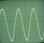
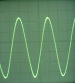
Here are some scope screenshots at 10kHz, without and with "complex" load.
The load is 4,7Ohms resistor with 0,1uF film polystyrene cap in parallel to it.
Output voltage swing is 4V peak-to-peak.
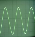
With sine signal, the load does not cause any effect, apart from some output sine reduction according to amp's output impedance (at the picture without load input and output sines are adjusted to be of the same amplitude at the screen. Afterwards, the load is connected).
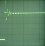
With square wave, the load does induce substabtial oscillations at the fronts (time scale of the picture with load is greatly extended). At this, I do not think that I should look for additional correction and speed down, since such sharp stimulus and load conditions can not exist in real life.
The load is 4,7Ohms resistor with 0,1uF film polystyrene cap in parallel to it.
Output voltage swing is 4V peak-to-peak.
With sine signal, the load does not cause any effect, apart from some output sine reduction according to amp's output impedance (at the picture without load input and output sines are adjusted to be of the same amplitude at the screen. Afterwards, the load is connected).
With square wave, the load does induce substabtial oscillations at the fronts (time scale of the picture with load is greatly extended). At this, I do not think that I should look for additional correction and speed down, since such sharp stimulus and load conditions can not exist in real life.
Attachments

Last edited:
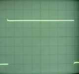
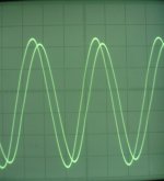
These three pictures refer to passband measurements with 4,7Ohms resistive load.
At 10kHz, input and output signals coincide at the scope's screen. Next two shots (at 100kHz and 1MHz) are taken after switchnig the frequency (input signal amplitude remains the same). Output signal amplitide starts to decrease, showing the passband limitation. At 1MHz I calculated near -0,7dB decrease in output amplitude compared to 10kHz.
At 10kHz, input and output signals coincide at the scope's screen. Next two shots (at 100kHz and 1MHz) are taken after switchnig the frequency (input signal amplitude remains the same). Output signal amplitide starts to decrease, showing the passband limitation. At 1MHz I calculated near -0,7dB decrease in output amplitude compared to 10kHz.
Attachments
With the values of caps indicated above (film 1, 10, 56, lytics 1000, 10000) I am shure we do not have resonances and ringing. Typical conditions for parasitic ringing are - small mica cap in parallel to big (10000uF) lytic. At high frequencies the lytic acts as L, and we come to self-oscillations at f=1/(6,28*sqrt(LC)), C is capacitance of the mica cap. With the fastest cap in the "sandwich" - film 1uF - we can not come to ringing, accounting fot resistive losses. Sometimes I separate big lytics by 0,025 Ohms resistors, but not because of ringing, just for decreasing participation of lytics at mid range.
Symmetrical rails solution does not remove the cap problem, it shifts the problem to one of rail, that will be included into output signal chain.
I did quite a lot of spice research on HF ringing from bypass caps and I suspect there will be some local ringing in voltage with 1uF bypass caps BUT because of the load impedance this may not translate into any ringing in current so sound may not be impacted. I posted some of my spice research on this here:
http://www.diyaudio.com/forums/sito-audio/217616-tssa-v1-6-docs-buyers-list-8.html#post3175798
. . . but only tested PSU caps in very low impedance environment and FB caps in much higher impedance environment. O/P cap impedance environment - typically 8 ohms - is somewhere between the two so would have to repeat with these tests for 8 ohms to clarify what happens at this impedance.
Personally I only go down to 4.7uF for bypass duties and always use 0.1 - 0.2 ohms in series. If several of these are used in parallel across a bank of electrolytic caps the characteristic electrolytic "sound" is substantially nuetralised.
On an output cap bank I would begin with at least 4 paralleled 4.7uF + 0.1R per channel so the resultant film cap series resistance is only 0.025 ohms
If you don't use very good sounding resistors for these snubbers much of the benefit will be lost - I use bare constantan wire - it sounds good.
edit: after doing some crossover design last year I know that investing in good quality caps gives substantial sonic rewards so for ultimate sound some spending is needed.
Balanced solution removes all these issues 🙂
Last edited:
I did quite a lot of spice research on HF ringing from bypass caps and I suspect there will be some local ringing in voltage with 1uF bypass caps BUT because of the load impedance this may not translate into any ringing in current so sound may not be impacted. I posted some of my spice research on this here:
http://www.diyaudio.com/forums/sito-audio/217616-tssa-v1-6-docs-buyers-list-8.html#post3175798
. . . but only tested PSU caps in very low impedance environment and FB caps in much higher impedance environment. O/P cap impedance environment - typically 8 ohms - is somewhere between the two so would have to repeat with these tests for 8 ohms to clarify what happens at this impedance.
Personally I only go down to 4.7uF for bypass duties and always use 0.1 - 0.2 ohms in series. If several of these are used in parallel across a bank of electrolytic caps the characteristic electrolytic "sound" is substantially nuetralised.
On an output cap bank I would begin with at least 4 paralleled 4.7uF + 0.1R per channel so the resultant film cap series resistance is only 0.025 ohms
If you don't use very good sounding resistors for these snubbers much of the benefit will be lost - I use bare constantan wire - it sounds good.
edit: after doing some crossover design last year I know that investing in good quality caps gives substantial sonic rewards so for ultimate sound some spending is needed.
Balanced solution removes all these issues 🙂
Thanks, Mike, for sharing this info. In your approach, its not evident for me that we should add series resistors to film caps. Rather I would prefer adding resistors to lytics. We also should remember that lytics have internal ESR around 0,02...0,1 Ohms.
I consider big lytics as "dirty" parts, that should be kept as far as possible from the active schematics. Their operation is subjected to various not finally established "anti-sound" mechanisms.
I did try to get better insite in what going on with shunts, I used precise immittance meter, and measured Z vs f curves. But I did not get repeating and illustrative results.
I 'd like also to warn about simulations of effects of big lytics at PS rails. Usually external distortion is added to the rail and penetration of the distortion to output is registered in the model. People conclude, look, if lytics produce distortions, we model them and see that they do not reach output. Their is a conceptual error here, the distortion from a lytic is not external, it is "generated" by the lytic itself, and formal C of the lytic can not further absorb this distortion. One should remove lytic's C from the model.
Last edited:
Yeah - with that many electrolytics you could add a small R to each one and the overall impedance is still low.
I will try this approach next time I make a cap bank - thx 4 the idea 🙂
But I still might add a small R to my film caps - I don't like the extreme uneven impedance vs frequency graph of film caps - prefer to remove that resonant impedance dip with some R.
I will try this approach next time I make a cap bank - thx 4 the idea 🙂
But I still might add a small R to my film caps - I don't like the extreme uneven impedance vs frequency graph of film caps - prefer to remove that resonant impedance dip with some R.
But I still might add a small R to my film caps - I don't like the extreme uneven impedance vs frequency graph of film caps - prefer to remove that resonant impedance dip with some R.
Sometimes I like to say, that the devil is not so terrible as results of his mathematical modelling. The shunting is less terrible if the cap is not in GNFB loop. But, if a cap is in the rail of high PSRR GNFB schematics, then everyone be afraid.
Balanced solution removes all these issues
What I see as problems of balanced solution:
1) Output impedance is doubled, and with MOSFET NoGNFB output stage it most likely will be around 0,5 Ohms (like that of a tube amp); and 0,2...0,3 Ohms with BJT output.
2) Current rating of power supply is four times more than that of SE stage with output cap (if standing current of SE is 1A into 4 Ohms and this allows for definite (current limited) undistorted output signal swing, than balanced has to have 2 x 2A for the same 1A output current ability into 4 Ohms, every part of the bridge operates on 2 Ohms load).
3) Output devices, current sources, etc., have definite "dead zones" of drain-gate and collector-emitter voltage utilization, that can not be used for signal swing. In balanced version the useless heat dissipation due to "dead zones" is four times higher.
4) Issues of zero voltage stability at output are essential.
5) Sonic advantages over SE with proper designed output cap are minimal.
Having in mind all these, one should decide.
I will make considered reply later but for now I just add one more point to your list:
6) We loose predominant 2nd harmonic distortion. Instead we have 3rd, 5th 7th 9th. Some think this will give a subjective disadvantage.
( Of course we can deliberately break symmetry to get 2nd back again if we are really missing it 🙂 )
6) We loose predominant 2nd harmonic distortion. Instead we have 3rd, 5th 7th 9th. Some think this will give a subjective disadvantage.
( Of course we can deliberately break symmetry to get 2nd back again if we are really missing it 🙂 )
About adding snubber resistors to either electrolytic or film caps.
I repeated this spice research with more care to get real world cap impedances and including an 8 ohm environment.
Adding some R to electrolytics: I checked your solution with 8 ohm impedance and as I suspected there is a resonance at around 300khz that shows itself very clearly in voltage across film cap but this does not have much effect in current passing through the load - it may be this does not have an audible impact in o/p cap usage however this method does produce a marked resonance in the current when used in a low impedance PSU rail environment.
Adding some R to film caps: This method does not produce a voltage or current resonance in either o/p cap or PSU rail cap environments but as you mention with OP caps it may allow the "sound" of the electrolytics to be heard more than with your method.
My provisional conclusion is we both probably found the best solution for the circuits we were working with but I will make a subjective comparison regarding OP caps when I build an OP follower stage.
What I see as problems of balanced solution:
1) Output impedance is doubled, and with MOSFET NoGNFB output stage it most likely will be around 0,5 Ohms (like that of a tube amp); and 0,2...0,3 Ohms with BJT output.
2) Current rating of power supply is four times more than that of SE stage with output cap (if standing current of SE is 1A into 4 Ohms and this allows for definite (current limited) undistorted output signal swing, than balanced has to have 2 x 2A for the same 1A output current ability into 4 Ohms, every part of the bridge operates on 2 Ohms load).
3) Output devices, current sources, etc., have definite "dead zones" of drain-gate and collector-emitter voltage utilization, that can not be used for signal swing. In balanced version the useless heat dissipation due to "dead zones" is four times higher.
4) Issues of zero voltage stability at output are essential.
5) Sonic advantages over SE with proper designed output cap are minimal.
Having in mind all these, one should decide.
Balanced vs unbalanced versions.
I have noticed that there are many different motivations expressed in this forum when designing audio equipment. Many want their designs or chosen projects to be:
1) simple
2) easy to build
3) cheap to build
4) cheap to run / efficient / "green"
5) use easily available parts
I'm sure these are all laudable goals but for me at present the only goal I have for my audio projects is that, within the realm of financial sanity, they sound as good as is possible. So my answers to your points above are made in this context.
1) The overall o/p impedance of my version of Pavel's design that I posted measured with 8ohm load is 0.13 ohms ( measured in spice ).
2) If I wanted an efficient amp I would not be considering any of these crazy class A designs ! With balanced we have to double the current but we can also reduce the voltage, so the overall power is only increased by about 44%. The advantage is that this amp can help to heat your house in the winter.
3) covered by last point but I think it is only 2 times more dead zones
4) Yeah, DC linked amps really need DC sense circuits to protect the load but these are not hard to design.
5) it may be a minimal gain but it is still a gain.
In addition to this there are several advantages to full balanced working.
1) Addional PSU noise reduction with common mode cancellation. In my experience thus far, lowering noise always gives sonic rewards.
2) Also common mode noise rejection from incoming signal.
3) Both legs of inputs and outputs have identical impedance character so there is maximum possible cancelation of RF interference
4) The system ground which, in unbalanced designs, is carrying the finest i/p signal currents is not dealing with massive loudspeaker current and it is not hanging out of the output of the amp like a huge antenna !
Actually it is my intention to build both versions of this kind of amp to make a comparison
Just thought it would be good to highlight the positive points of balanced working 🙂
Last edited:
About adding snubber resistors to either electrolytic or film caps.
I repeated this spice research with more care to get real world cap impedances and including an 8 ohm environment.
Adding some R to electrolytics: I checked your solution with 8 ohm impedance and as I suspected there is a resonance at around 300khz that shows itself very clearly in voltage across film cap but this does not have much effect in current passing through the load - it may be this does not have an audible impact in o/p cap usage however this method does produce a marked resonance in the current when used in a low impedance PSU rail environment.
Adding some R to film caps: This method does not produce a voltage or current resonance in either o/p cap or PSU rail cap environments but as you mention with OP caps it may allow the "sound" of the electrolytics to be heard more than with your method.
My provisional conclusion is we both probably found the best solution for the circuits we were working with but I will make a subjective comparison regarding OP caps when I build an OP follower stage.
Mike, thanks a lot for this info. In addition to this, I would be grateful for your summary words, about what exactly L forms resonance with C of the film cap. Is it L of an individual 1000uF lytic, or L related to 24 paralleled lytics like in my amp? What is the way to reduce resonance, inevitable R in series to film cap?
Of course every implementation will be different and with some good surface mount film caps the problem might be quite a bit less.
I add inductance according to the formula of 1nH per mm of leads plus some film cap internal inductance. Looking around online I found the lowest internal R of film caps ( at resonance ) was about 0.005 ohms so I used this as a worst case scenario.
I was playing with different methods to get best solution for PSU rail caps and ended with:
10uF + 0.1R in parallel with 4.7uF + 0.1R in parallel with 1.0uF + 0.2R.
This gave a nice smooth impedance curve
In the "frightening world" of global FB amps adopting these measures is essential. My ears are crying with pain if I fail to use these measures.
But I suspect that erradicating micro resonances in all parts of every audio circuit is essential if we really want the very best results.
The "better" the film cap the lower is it's ESR.
That makes ringing more likely.
One requires a capacitor that is bad for ESR to give the least chance of ringing. X7R gives this higher ESR.
That makes ringing more likely.
One requires a capacitor that is bad for ESR to give the least chance of ringing. X7R gives this higher ESR.
The "better" the film cap the lower is it's ESR.
That makes ringing more likely.
One requires a capacitor that is bad for ESR to give the least chance of ringing. X7R gives this higher ESR.
There exist also copper-foil and silver-foil film caps, and possible ringing does not prevent using them, due to their superior sound quality. And, I guess, their ESR is the lowest due to silver film (compared to deposited stannum film).
By this I would like to say, that even if X7R seems convenient theoretically, the superior judge (sound) is to read the sentence.
Member
Joined 2009
Paid Member
Hi Vladimirk,
I took another look at your design to learn a bit more. I’m not sure if I understand it all but here’s a few comments that if wrong, you must correct or it means I didn’t understand it !
The input is a JFET-MOSFET pair in a topology similar to Sziklai-with-gain, it contains a localized feedback loop which improves linearity, lowers output impedance and can provide plenty of current. The JFET input device has enough gate-drain capacitance to prevent oscillations around this local feedback loop. A very nice input stage, off to a good start !
You have a fully regulated power supply for the front end that starts with a series regulator (T4 is a current source for the zener diode string which holds gate of the T3 source follower at a clean reference voltage) followed by a shunt regulator (current source and zener structure). The shunt regulator provides a return path for a.c. currents that flow through the input stage. I call this approach the ‘electronic capacitor’ because it replaces the usual need for a power-rail capacitor. To say this is better than a capacitor is to say that the ‘zener structure’ is better than a capacitor. Is this really the case ?
The output stage is triple-Darlington loaded on a current source. There is a series regulated power supply. The output stage is capacitively coupled through the speaker to ground. The current source load removes any signal from the power rails. The output capacitor is directly in the signal path and must flow high current with low impedance - it needs to be large.
You chose -Ve rail single supply, you want to have the output signal currents circulate back to the gnd and you want to use NPN transistors. If you used more traditional +ve single rail you would have to use PNP. You could eliminate the output capacitor with a bridged design (or a large shunt regulator), but it would be even less power efficient.
Question: an alternative approach is to allow the output signal current to flow through the power rail, meaning you have both an output capacitor and a power rail capacitor. The power rail can still be regulated to make it clean and to isolate it from the power supply. Then you would be free to modulate the current source in sympathy with the signal. This is the approach that I see taken by Nelson in the Aleph, and by Wavebourn in his Tower and perhaps you might say the JLH 1969. I believe the reason is that a modulated current source load for the output responds better to real-world loads. Did you try this approach in comparison ?
Bigun, thaks a lot for your consideration of this schematics, and I confirm that you have mentioned the main specific solutions used. I'll try to do my best in providing reasons for them, during the next day. Of course, there are some reasons, based mainly on my personal experience. I am really grateful for your friendly concern.Hi Vladimirk,
I took another look at your design to learn a bit more. I’m not sure if I understand it all but here’s a few comments that if wrong, you must correct or it means I didn’t understand it !
The input is a JFET-MOSFET pair in a topology similar to Sziklai-with-gain, it contains a localized feedback loop which improves linearity, lowers output impedance and can provide plenty of current. The JFET input device has enough gate-drain capacitance to prevent oscillations around this local feedback loop. A very nice input stage, off to a good start !
You have a fully regulated power supply for the front end that starts with a series regulator (T4 is a current source for the zener diode string which holds gate of the T3 source follower at a clean reference voltage) followed by a shunt regulator (current source and zener structure). The shunt regulator provides a return path for a.c. currents that flow through the input stage. I call this approach the ‘electronic capacitor’ because it replaces the usual need for a power-rail capacitor. To say this is better than a capacitor is to say that the ‘zener structure’ is better than a capacitor. Is this really the case ?
The output stage is triple-Darlington loaded on a current source. There is a series regulated power supply. The output stage is capacitively coupled through the speaker to ground. The current source load removes any signal from the power rails. The output capacitor is directly in the signal path and must flow high current with low impedance - it needs to be large.
You chose -Ve rail single supply, you want to have the output signal currents circulate back to the gnd and you want to use NPN transistors. If you used more traditional +ve single rail you would have to use PNP. You could eliminate the output capacitor with a bridged design (or a large shunt regulator), but it would be even less power efficient.
Question: an alternative approach is to allow the output signal current to flow through the power rail, meaning you have both an output capacitor and a power rail capacitor. The power rail can still be regulated to make it clean and to isolate it from the power supply. Then you would be free to modulate the current source in sympathy with the signal. This is the approach that I see taken by Nelson in the Aleph, and by Wavebourn in his Tower and perhaps you might say the JLH 1969. I believe the reason is that a modulated current source load for the output responds better to real-world loads. Did you try this approach in comparison ?
You have a fully regulated power supply for the front end that starts with a series regulator (T4 is a current source for the zener diode string which holds gate of the T3 source follower at a clean reference voltage) followed by a shunt regulator (current source and zener structure). The shunt regulator provides a return path for a.c. currents that flow through the input stage. I call this approach the ‘electronic capacitor’ because it replaces the usual need for a power-rail capacitor. To say this is better than a capacitor is to say that the ‘zener structure’ is better than a capacitor. Is this really the case ?
Let's go step by step. About this specific question:
Previously I believed that the shunt power supply is a pretty stupid decision, because it waste energy and creates design difficulties with heat dissipation . Quality series voltage regulators seemed to be providing all the necessities. This view changed after experimenting with a simple common source amplification stage. Kp903 fet was used at the input, and above it – high-voltage SIT transistor kp926 as a cascode. Another kp926 with gate-source resistor was used as a dynamic load. Supply voltage was provided by 140V series stab, rather high voltage in order to improve linearity at typical output voltages 1 ... 10 volts. This solution resembles the tube stage, but with " solid state tubes “ - SIT transistors. I expected to get a detailed, “emotional”, sound, a sample of which I have from a good SE 300B tube amp. At the same time, the ability to evaluate sound was provided due to high quality of other system components (PMC EB1i speakers, Stereovox 600 silver speaker cables, Analysis Plus Silver Oval-In RCA interconnects, Shanling CD-T1500 player with matched pairs of nos Philips E88CC SQ tubes). I mention this, because the sound expertise based on ordinary Mid-Fi system is almost impossible, the listener often can not distinguish the effect of the changes undertaken.
The first result of the evaluation of SS preamp was a disappointment. Its inclusion in the system immediately made sound muddy, emotional component was lost, a typical Mid-Fi sound. The implication was that transistors – are transistors, and tubes – are tubes, and the results of their use can not be similar.
Then the modification was made, polypropylene 80uF cap was used instead the electrolytic capacitor on the power supply rail. Character of the sound has improved substantially, but not to the level of a good tube device. Adding polypropylene 1 ... 15 uF shunts, also as RC with small R in series, gave changes at small nuances.
An idea of the next step came out from a desire to imitate the type of the tube amp power supply - choke input LC filter. The question was, what is the effect of the input choke, only decreasing 100Hz ripples of the rectified voltage, or something else. One can reduce the ripples easier and less costly – by RCRC filters. If power supply consists of the rectifier diode bridge, RCRC filter and series voltage regulator, then during the “open state” period of the rectifier diodes, the output signal current is circled, partially via PS caps, and partly through the secondary winding of the transformer, which can be affected by the high-frequency components of non-ideal mains voltage. In the case of the input choke, "dirt" from the power supply can not penetrate. Hence came the idea of using a shunt voltage regulator, in addition to existing series stab. Shunt power supply comprises a current source with high dynamic resistance, and a reg transistor connected in parallel to load. Current source decouples the diode bridge rectifier and power transformer. The result of the implementation of this idea was the "merger" of the SS world with the tube world, in the sense of the sound characteristics.
One of the conclusions from result - PS capacitors alone can not exclude the participation of power supply components in the signal currents, the power supply is to be separated from the main circuit by the choke or by current source. The second variant is preferable for me, because one can reduce the physical dimensions of the device in which the signal currents are localized. It is important for the suppression of electromagnetic interactions, harmful for micro-level signal components. Moreover, typical "SS PS chokes" of mH range are much less efficient than "a lot of Henry tube PS chokes".
By describing this example, I do not pretend to state, that similar good sound result is impossible with ordinary series-reg approach, but the last needs incomparably more investigations and assembling tricks, that will be valid for the specific design only.
Last edited:
- Status
- Not open for further replies.
- Home
- Amplifiers
- Solid State
- Rails Decoupled SE Amplifier