Yes input buffers work at 12V with this xformers or like ZM solution.I don’t talk about the biasing circuits, but the input buffers…
🙄
Hi Permanender🙂
This CSX1 version must have other transformer with 12V outputs
I like very much PCB you made for SIT CSS with
IXYS transistors together with SK82.
For VFet Papa one it be very elegant solution to menage PSU and
regulated with signal at 2 or 3 distinct PCB´s version CSX2 or CSX2
with buffer or without for one mono chanel.
Cheers 😀
Oooops i was want say CSX1 or CSX2
🙂
I asked about the Jensen audio Transformer. The question final is which one. Does is the 370KHz or the 270KHz? AUDIO TRANSFORMER.
Nobody thank in use SMPS?
Is this the easiest form? or
Am I talking heresies?
Using a rail of 12volts coming from the same output rail could intermodulate the buffer. In the A75 uses a high voltage in the buffer, something like ten volts per rail from a different power supply.
OK gentleman I received only one message from the thread and you sent along the morning, more than five post.
Oh, this is kinda neat and nice! me like. me like.
Why not try to make this a little bit more like a "real" amplifier (one that can drive more normal sensitivity/uneven impedance curve)
I'm thinking about 2-4 output pairs. I am no expert but wouldn't 4 pairs lower the output impedance to ~1 ohm without feedback? (ofc. the transformer and driving source has to handle the input capacitances of multiple gates)
How does the bias/output impedance relate to each other here?
Maybe even go higher on the main rails to get ~50W @8ohm too?
How does one calculate the gain on there amps/devices? paralleling the transconductance of all the outputs?
I think it's unpractical to start go above ~3A @+-25v in bias current per channel (or above 150W dissipation per output-SIT-pairs and per channel)
Love to you Nelson, my second dad!
I guess part 2 or 3 or something will give you the answer. And also drain Acronman's supply.... We will all have to write to Sony's chairman and ask for more!!!!!!!
Welcome Chris:
The Vfets scarce. Are hard to find, expensive. We have a project now. Easy almost Zen. Later we can encourage the energy for another one. Similar or not. Anyway if you discover the endless quantity of designs and topologies that NPass make every time.
Please attach yourself to this and later we gonna work together in a more ambitious design.
Like the invention by Mr. Pass he named STASIS; which maybe adapted to either VFET amps for example by using boosters of the bilateral output current.Welcome Chris:
The Vfets scarce. Are hard to find, expensive. We have a project now. Easy almost Zen. Later we can encourage the energy for another one. Similar or not. Anyway if you discover the endless quantity of designs and topologies that NPass make every time.
Please attach yourself to this and later we gonna work together in a more ambitious design.
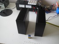
VFET Amp heatsinks arrived yesterday 🙂
I have some questions, I have two options for placing the 4 sinks, see pictures.
First picture is to make a nice cube like Amp without the PSU transformers, they will be in a separate enclosure. So no influence with the Jensens.
Second picture is the conventional 19 inch setup, PSU transformers in front and the Jensen at the backplate connected to the inputs.
But where do I best cut the PSU if I do the cube? Should I just put the transformers in the separate enclosure, and feed the cube with AC?
Or do I put the rectifiers and the CRC also in it, and feed that to the cube?
The voltage regulator MOSFETs will be together with a VFET on one sink each.
Sinks are 0.4K/W each, so they should be just fine to hold the 36 Watt of the VFET and the approx.. 15 Watt of the MOSFET.
Thanks!
Attachments

Hello WalterW. I see in your pics at least 16 TO-3 devices in styrofoam cradles. VFETs? What's with the 9 VDC battery; a reference for relative size and/or for Vgs biasing?
Best regards
Best regards
Yep, my VFETS ( KE33) from Acronman, I hope to build ( and listen to) all the Amps in the articles Nelson is writing😀
The 9V battery is for size reference.
Love your posts here at DIYAudio, Antoinel !
The 9V battery is for size reference.
Love your posts here at DIYAudio, Antoinel !

I am going for "The Beast with A Thousand V-FETs". Or "The Return of The SIT". Whatever makes you smile!
considering amount of watts I usually need , I'm waiting for Papa's article about one transistor stereo amp preferably with 2N3055
then I'm heading of to Greedy Boy Retirement , being good with DIY and Graal and 42

(dunno what to do then with mountain of parts )
then I'm heading of to Greedy Boy Retirement , being good with DIY and Graal and 42
(dunno what to do then with mountain of parts )
Does this non-inexpensive transformer fit the bill (available in silver for even more!)
http://www.lundahl.se/pdf/1948.pdf
Kinda glad I already got the Jensen ones.
http://www.lundahl.se/pdf/1948.pdf
Kinda glad I already got the Jensen ones.
ZM, I am sorry I moved into "off-topic thread territory".
However, I will try to make it good again.
Someone here asked about paralleling devices. Could this also be done with a common source topology as these CSX1 amplifiers are?
However, I will try to make it good again.
Someone here asked about paralleling devices. Could this also be done with a common source topology as these CSX1 amplifiers are?
Does this non-inexpensive transformer fit the bill (available in silver for even more!)
http://www.lundahl.se/pdf/1948.pdf
Kinda glad I already got the Jensen ones.
I like Lundahl , but I don't like lack of (to me ) veeeery important value - L of windings
however - they're looking as proper repeater coils , so answer is - most probably yes
tough - if Papa tried it (something) , look no further ; he's having that white hair for reason
ZM, I am sorry I moved into "off-topic thread territory".
However, I will try to make it good again.
Someone here asked about paralleling devices. Could this also be done with a common source topology as these CSX1 amplifiers are?
I feel cozy there ... no urge to feel important and to know anything

as long drive is firm , paralleling those devices isn't critical ; Pa thought us (few clever chaps around , too ) that paralleling result in increase of xconductance , so OLG , so capacitances aren't linearly worse ........
But where do I best cut the PSU if I do the cube? Should I just put the transformers in the separate enclosure, and feed the cube with AC?
Or do I put the rectifiers and the CRC also in it, and feed that to the cube?
Anybody? This is new territory for me....
- Status
- Not open for further replies.
- Home
- Amplifiers
- Pass Labs
- Article - Sony VFETs part 1