Member
Joined 2009
Paid Member
D
Deleted member 148505
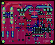
The trace I can see has resulted in a slot in the ground plane.
Is there a way to avoid that slot?
We can place vias parallel with the input trace, so that the top signal gnd plane will appear continuous, and the top and bottom plane will be connected in many points (through the vias).
Member
Joined 2009
Paid Member
Not sure if included (didn't see it on your Eagle schematic) but a pair of reversed diodes is often a good precaution across R3 (ground lift resistor) and across the feedback cap - Hugh used them on his version.
I would also add a footprint for an alternative input cap, a small bipolar electrolytic. Just add a cap to the schematic in parallel to the existing one. I have found that a good quality (Nichicon audio grade) bipolar cap of at least 10uF (I've used 100uF) to sound very good.
Maybe ensure you have the right footprints for the caps for the sizes you might want to try - I used a 50V Nichicon MUSE audio grade cap for the bootstrap (I used 200uF) and 100uF for the power rail decoupling capacitor above the LTP (it does impact the sound in subtle ways).
Last edited:
D
Deleted member 148505
Not sure if included (didn't see it on your Eagle schematic) but a pair of reversed diodes is often a good precaution across R3 (ground lift resistor) and across the feedback cap - Hugh used them on his version.
I would also add a footprint for an alternative input cap, a small bipolar electrolytic. Just add a cap to the schematic in parallel to the existing one. I have found that a good quality (Nichicon audio grade) bipolar cap of at least 10uF (I've used 100uF) to sound very good.
The footprint of ground lift resistor can accommodate 2 to 3 watts 10 ohms, so I think the back to back diodes will not be needed.?
The footprint for decoupling cap in LTP is 10.5mm diameter, it's enough for 220uf 50v. Bootstrap cap is oversized, 13mm diameter 🙂
I'll post the changes tomorrow, it's late here. Thanks for the suggestions 🙂
Last edited by a moderator:
I agree, R5 is not needed (and wasn't part of the original AKSA). R13 was part of the feedback circuit designed by Hugh - he had reasons for it that escape me right now.
R13 has been part of the AKSA circuit since the P61 days. The resistor is shown on Hugh's conceptual schematic but without values. If you can find an old P61 schematic you might find some values.
re Posts 709 and 713
R13 is there to speed up the amplifiers' recovery from clipping. See the Rod Elliot article at Power Amplifier Clipping
R5 is there to limit the dissipation in T1 (the input transistor) if the amplifier is driven heavily into overload.
pb
Thanks Paul. R13, I always wondered why. The values shown on Rod's schematic are no where correct for the AKSA.
I'd be careful about adding R5, with the component values I show in the BAKSA schematic get you close to zero DC offset.
regards
Not sure if included (didn't see it on your Eagle schematic) but a pair of reversed diodes is often a good precaution across R3 (ground lift resistor) and across the feedback cap - Hugh used them on his version.
The diodes are not used on any of the AKSA 55's that I am aware of, although where were long discussions about adding them.
Hugh may have added them on the AKSA 100's and NAKSA's. I don't know.
My "real" AKSA 55's have run perfectly of 10 years without them. That's >10 hours a day, 7 days a week. No failures what so ever.
regards
I would also add a footprint for an alternative input cap, a small bipolar electrolytic. Just add a cap to the schematic in parallel to the existing one. I have found that a good quality (Nichicon audio grade) bipolar cap of at least 10uF (I've used 100uF) to sound very good.)
Yes a good idea. My current AKSA 55 one has small electrolytic. I use 1uF MMK on the BAKSA.
Maybe ensure you have the right footprints for the caps for the sizes you might want to try - I used a 50V Nichicon MUSE audio grade cap for the bootstrap (I used 200uF) and 100uF for the power rail decoupling capacitor above the LTP (it does impact the sound in subtle ways).
The bootstrap cap seems to affect the soundstage. Rabbitz also recommends MUSE in this location. I have used generic, Blackgate and MUSE and settled on the MUSE (all 100uF) although the Blackgate was more detailed and precise. Worth experimenting!
regards
I also used 1/4w 100 ohm resistor in parallel with the fuse before (as with orig hugh's design). What happened to my amp was after the fuse was blown, the resistor just smoked and messed the PCB with ash traces. That's why I decided to put LEDs instead of resistors for blown fuse indicator.
Unfortunately you didn't have access to Hugh's wonderful construction manual. These resistors need to be mounted off the PCB so they don't cause damage. Hugh also placed them underboard for easy access if they need replacing and so they don't damage other components. The smoke and smell ARE the indicators of a problem.
I bet you will hear the problem, then smell the problem before you notice a LED is not illuminated.
regards
5V is what it takes to go over 250mW for a 100R resistor. That's enough to LIGHT an LED if it's placed across the fuse in place of the resistor. A high brightness red or electric blue LED would get your attention.
A high brightness red or electric blue LED would get your attention.
Only if you are sitting in the same room as the amp 😀
How about an input into your fire alarm system? 😉
D
Deleted member 148505
You can find the P61 Schematic in Wayback Machine, can't really remove something on the internet once you posted them. 🙁R13 has been part of the AKSA circuit since the P61 days. The resistor is shown on Hugh's conceptual schematic but without values. If you can find an old P61 schematic you might find some values.
Unfortunately you didn't have access to Hugh's wonderful construction manual. These resistors need to be mounted off the PCB so they don't cause damage. Hugh also placed them underboard for easy access if they need replacing and so they don't damage other components. The smoke and smell ARE the indicators of a problem.
I bet you will hear the problem, then smell the problem before you notice a LED is not illuminated.
regards
Yes, I didn't have access, but I anticipated the ash traces because Hugh told that the smoke will be the indicator of problem so I slightly raised the resistor on the PCB. But not high enough, the resistor burned spectacularly, I should have elevated them more 😱
By the way, here are the changes 🙂
The back to back electro input cap can be joined with a solder blob. I put bstop on its top trace.
Attachments
Last edited by a moderator:
if the Fault Current is ONLY 500Apk, what voltage will the Power resistor drop?.............ground lift resistor can accommodate 2 to 3 watts 10 ohms, so I think the back to back diodes will not be needed.?
..................
Will the Power Resistor fail before the Mains Fuse Blows?
Normal Peak Fault Current can be a few thousand amperes. This is what blows the Mains Fuse very quickly.
D
Deleted member 148505
if the Fault Current is ONLY 500Apk, what voltage will the Power resistor drop?
Will the Power Resistor fail before the Mains Fuse Blows?
Normal Peak Fault Current can be a few thousand amperes. This is what blows the Mains Fuse very quickly.
I was referring to the ground lift for the signal ground. I don't think there will be large surge current that will flow into it. Even if there is, the suggested back to back 1n4148 or 4007 will have no help for it.
Last edited by a moderator:
Member
Joined 2009
Paid Member
It's more a precaution against fault conditions, only then would you expect much current. The thing is, depending on your overall scheme, it may also be a matter of safety to ensure that the ground lift resistor is not compromised.
I too was referring to the resistor inserted between the interconnect cable and the Chassis.I was referring to the ground lift for the signal ground. I don't think there will be large surge current that will flow into it. Even if there is, the suggested back to back 1n4148 or 4007 will have no help for it.
This resistor is in the route of Fault Current if there is catastrophic failure in any of the Source components. Many of these Source components do not have a Safety Earth fitted, because they are double insulated.
The Mains fuse cannot blow if the Mains Current cannot escape.
You connect a dangerously wired Amplifier to one of those Faulty Source components and you have created a death trap.
This resistor is in the route of Fault Current if there is catastrophic failure in any of the Source components. Many of these Source components do not have a Safety Earth fitted, because they are double insulated.
A few random thoughts....
How long would the thin signal traces last on the PCB under such fault conditions? Would they blow before the fuse? Are we sizing these traces properly?
To do things safely, the RCA plugs need to be directly earthed to the safety earth with proper sized wire. Ground loops?
What is the rating of RCA cables? These must also be rated to carry the fault current?
Does anyone have the facilities to test the PCB traces and RCA cables? I'd be interested in the results.
regards
Double insulated appliances are for sale only because they satisfy the standards required of double insulated appliances to certify they are safe. If you plan to rely on the interconnect shield as a safety earth for your source then you are going beyond what the NEC has considered diminishing returns in safety AFAIK. Is it more or less likely to have a car accident than it is to get shocked by a double-insulated appliance?
If you are this worried about your source then you should also check your toaster, and every other 2-prong appliance in your house. I don't think any of them will have a place to attach a ground wire. Honestly I would be more worried about the toaster, and I think statistics confirm this.
If you are this worried about your source then you should also check your toaster, and every other 2-prong appliance in your house. I don't think any of them will have a place to attach a ground wire. Honestly I would be more worried about the toaster, and I think statistics confirm this.
D
Deleted member 148505
I too was referring to the resistor inserted between the interconnect cable and the Chassis.
This resistor is in the route of Fault Current if there is catastrophic failure in any of the Source components. Many of these Source components do not have a Safety Earth fitted, because they are double insulated.
The Mains fuse cannot blow if the Mains Current cannot escape.
You connect a dangerously wired Amplifier to one of those Faulty Source components and you have created a death trap.
Indeed, the back to back diodes is better installed in that case. Otherwise, the ground lift resistor will act as a load to the source device.
But the designers of the source device should have defined the over current condition of the device, otherwise it was a neglect on their part if in that case the source device fuse didn't blow or any protection circuit didn't trigger.
Hi All,
I am new here, I have read this thread but not all though as I might have skipped some comments. I am now planning to build this amplifier! =) One question though. What is the maximum supply voltage and what is the maximum power it can deliver? maybe it was posted here I have just missed it.
Considering only two OP Transistor.
TIA
Ren
- Home
- Amplifiers
- Solid State
- Based on Hugh Dean's AKSA 55