You are a handsome gringo, Renato!
Wonderful to hear Brazilian Portuguese, a very pretty language to me.
To repeat Greg: Did people like the sound? It seemed to me from the video that the top end was very clear and sharp, yet warm....... hard to tell with compressed music.
Ciao from Oz,
Hugh
Wonderful to hear Brazilian Portuguese, a very pretty language to me.
To repeat Greg: Did people like the sound? It seemed to me from the video that the top end was very clear and sharp, yet warm....... hard to tell with compressed music.
Ciao from Oz,
Hugh
Hi farjon,
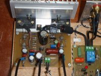
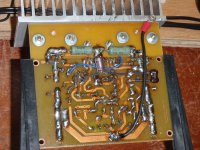
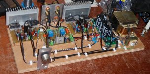
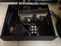
Any chance you could post some close up pictures of the amp.
Was the amp well received?
regards
Yes, see attachments.
Yes, the amp was well received. 😀
In this vídeo, the audio was retained. Although is necessary Facebook login...
https://www.facebook.com/photo.php?v=734420906586589&set=o.710782142285278&type=2&theater
Regards,
Sergio.
Attachments
Yes, see attachments.
Yes, the amp was well received. 😀
In this vídeo, the audio was retained. Although is necessary Facebook login...
https://www.facebook.com/photo.php?v=734420906586589&set=o.710782142285278&type=2&theater
Regards,
Sergio.
Thanks Sergio for posting the pictures. Nice work btw. I see you did post a picture a few pages ago but I didn't make the connection. 😕
I noticed you did a few mods... I am having a close look now.

Unfortunately I have facebook blocked so I can't see the facebook clip.
regards
hi Sergio,
My memory must be failing big time or.... I'm blaming it on your name change. 😀
Thanks for showing me....(again)!
BTW: I added your output devices to this list: Output Transistors
regards
BTW: I added your output devices to this list: Output Transistors
Greg,
These devices were discontinued. Better exchange to 2sc3858 / 2sa1494.
http://www.sanken-ele.co.jp/en/prod/semicon/pdf/2sc3858e.pdf
And the 2sc2922 current is 17A, not 27A...
http://www.sanken-ele.co.jp/en/prod/semicon/pdf/2sc2922e.pdf
Rgds.
Last edited:
Greg,
These devices were discontinued. Better exchange to 2sc3858 / 2sa1494.
http://www.sanken-ele.co.jp/en/prod/semicon/pdf/2sc3858e.pdf
And the 2sc2922 current is 17A, not 27A...
http://www.sanken-ele.co.jp/en/prod/semicon/pdf/2sc2922e.pdf
Rgds.
Done.
D
Deleted member 148505
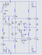
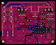
I completed my BAKSA amp recently and I instantly loved the sound, that's why I created a PCB for it and will add it to my DIY amp collection at home 🙂 The schem uploaded is my preferred sound.
Attachments
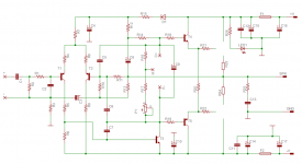
That schematic is missing some things. 🙂
PS, I think this REALLY deserves more attention:
http://www.diyaudio.com/forums/solid-state/168554-based-hugh-deans-aksa-55-a.html#post3757677
PS, I think this REALLY deserves more attention:
http://www.diyaudio.com/forums/solid-state/168554-based-hugh-deans-aksa-55-a.html#post3757677
Member
Joined 2009
Paid Member
I agree, R5 is not needed (and wasn't part of the original AKSA). R13 was part of the feedback circuit designed by Hugh - he had reasons for it that escape me right now.
R5 and R9 might be needed to lower the temperature of the input transistors. They have an effect on RF behavior and if large enough may affect compensation.
That schematic may have been copied wrong. R13 may have been a copying error and I've seen this happen before. If it's not an error, then this resistor will serve to increase current through C3 and lower the feedback side corner frequency. I don't see any requirement for this resistor electrically, so any purpose it must have is something to do with altering the sound. Perhaps it would be interesting to replace it with a trimmer and make observations?
That schematic may have been copied wrong. R13 may have been a copying error and I've seen this happen before. If it's not an error, then this resistor will serve to increase current through C3 and lower the feedback side corner frequency. I don't see any requirement for this resistor electrically, so any purpose it must have is something to do with altering the sound. Perhaps it would be interesting to replace it with a trimmer and make observations?
re Posts 709 and 713
R13 is there to speed up the amplifiers' recovery from clipping. See the Rod Elliot article at Power Amplifier Clipping
R5 is there to limit the dissipation in T1 (the input transistor) if the amplifier is driven heavily into overload.
pb
R13 is there to speed up the amplifiers' recovery from clipping. See the Rod Elliot article at Power Amplifier Clipping
R5 is there to limit the dissipation in T1 (the input transistor) if the amplifier is driven heavily into overload.
pb
D
Deleted member 148505
Layout update:
Moved the rail tracks under the PCB.
Added SMD LEDs under fuses.
🙂
Moved the rail tracks under the PCB.
Added SMD LEDs under fuses.
🙂
Attachments
Last edited by a moderator:
Member
Joined 2009
Paid Member
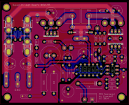
If R23 and R24 are big 5W ceramic resistors you might want to be careful about vertical mounting them. They are large and easily knocked - which puts severe strain on the solder pad underneath them. Another option is to use multiple 2W resistors in parallel.
Hugh put 2W resistors in parallel with the fuse holders (around 100R). This way, if one fuse inadvertently blows the resistor will keep the rail up at lower current and help avoid a large dc at the output. It also allows you to power up the amplifier without load to check some basic things without allowing full current so that you can avoid blowing up output devices if the idle current is at the wrong end of the adjustment range when you are building it. These 100R resistors get hot very fast but I did find them useful in my own version (called TGM).
Can you make the power traces wider ?
Last edited:
Can you move C12 so that it points towards C11?
There's room at the N of NPN.
Can you move the input trace feeding C1 to the top side?
That gets rid of the slot in the signal ground plane.
There's room at the N of NPN.
Can you move the input trace feeding C1 to the top side?
That gets rid of the slot in the signal ground plane.
D
Deleted member 148505
Hugh put 2W resistors in parallel with the fuse holders (around 100R). This way, if one fuse inadvertently blows the resistor will keep the rail up at lower current and help avoid a large dc at the output. It also allows you to power up the amplifier without load to check some basic things without allowing full current so that you can avoid blowing up output devices if the idle current is at the wrong end of the adjustment range when you are building it. These 100R resistors get hot very fast but I did find them useful in my own version (called TGM).
Can you make the power traces wider ?
Yes they are big 5W ceramic resistors, I increased the solder pad to triple the default value from eagle. Nice idea, I'll provide holes for 2W parallel resistors
I also used 1/4w 100 ohm resistor in parallel with the fuse before (as with orig hugh's design). What happened to my amp was after the fuse was blown, the resistor just smoked and messed the PCB with ash traces. That's why I decided to put LEDs instead of resistors for blown fuse indicator.
Hugh put limits to the adjustment of idle current adjustment through R17. So risking of blowing up the output devices was reduced. I suggest just put 2W resistors in place of fuses when testing instead of putting it permanently on the PCB.
Yes I can make the negative rail track wider.

Last edited by a moderator:
D
Deleted member 148505
Nice suggestion, I'll squeeze the space to move C12 closer to the O/P transistor pin.Can you move C12 so that it points towards C11?
There's room at the N of NPN.
Can you move the input trace feeding C1 to the top side?
That gets rid of the slot in the signal ground plane.
Can't understand this, the input trace for C1 is on top side. There's a signal ground plane on top (red) and bottom (blue).
For the record, I won't sell this on ebay, I just posted my layout for gallery and scrutiny purposes.
Thanks!
- Home
- Amplifiers
- Solid State
- Based on Hugh Dean's AKSA 55