Hi,
After successfully building my 250W amp, I designed it's low power version with some improvements. as 100W is sufficient enough for home use I removed two output pairs from 4 lowered the rails a bit, now we have a decent 100W into 8 ohm amp.
Simulated it in multisim, and below are some figures:
Supply voltage: +/-50V DC
Power output: 135W into 8, 260W into 4ohms
THD20: 0.005% @ 135W into 8 ohm load
THD1: 0.001% @ 135W into 8 ohm load
I designed the PCB in sprint layout, got them manufactured locally along with the power supply PCBs.
 [/URL][/IMG]
 [/URL][/IMG]
 [/URL][/IMG]
 [/URL][/IMG]
 [/URL][/IMG]
 [/URL][/IMG]
 [/URL][/IMG]
 [/URL][/IMG]
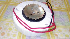
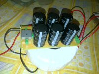
Power supply with 66000uF of Nichicon capacitance per rail, 35-0-35, 500VA toroid.
Sound is very good, powerful bass and very detailed and open mids, highs.
Here's the link to the video: DIY 120W amplifier sound test - YouTube
Cheers!!🙂
Aniket
After successfully building my 250W amp, I designed it's low power version with some improvements. as 100W is sufficient enough for home use I removed two output pairs from 4 lowered the rails a bit, now we have a decent 100W into 8 ohm amp.
Simulated it in multisim, and below are some figures:
Supply voltage: +/-50V DC
Power output: 135W into 8, 260W into 4ohms
THD20: 0.005% @ 135W into 8 ohm load
THD1: 0.001% @ 135W into 8 ohm load
I designed the PCB in sprint layout, got them manufactured locally along with the power supply PCBs.
Power supply with 66000uF of Nichicon capacitance per rail, 35-0-35, 500VA toroid.
Sound is very good, powerful bass and very detailed and open mids, highs.
Here's the link to the video: DIY 120W amplifier sound test - YouTube
Cheers!!🙂
Aniket
Attachments
Last edited:
What are the voltages this amplifier can drive into 8r0 and 4r0 test loads without clipping of the signal?
32.86V and 32.2V rms into 8 and 4 ohm load respectively(Based on simulation).
In practical, it would conservatively do ~120W into 8ohms(+/-50V DC rails).
In practical, it would conservatively do ~120W into 8ohms(+/-50V DC rails).
you have built it.Power supply with 66000uF of Nichicon capacitance, 35-0-35, 500VA toroid.
What are the measurements?
Nice design!
Can you hear any noise/hum when there is no music playing to check the floor noise?
What is the max input signal before it clips?
What about pop/click noise when you power up/down?
I can see a big heatsink there, how is the thermal dissipation? Have you been able to measure the temperature?
Can you hear any noise/hum when there is no music playing to check the floor noise?
What is the max input signal before it clips?
What about pop/click noise when you power up/down?
I can see a big heatsink there, how is the thermal dissipation? Have you been able to measure the temperature?
you have built it.
What are the measurements?
I got it manufactured locally here in Delhi, it's 175mm wide, 65mm tall, weighs ~6.5 kg.
Nice design!
Can you hear any noise/hum when there is no music playing to check the floor noise?
What is the max input signal before it clips?
What about pop/click noise when you power up/down?
I can see a big heatsink there, how is the thermal dissipation? Have you been able to measure the temperature?
Amplifier is dead silent, even if I put my ears close to the tweeters, no hiss no hum.
Input signal is 1.7V to drive it into clipping.
I biased it at 7.6mV across the 0R22 resistor, that equates to ~35mA per device. The heatsink was warm, not hot when the bias stabilized.
Regards,
Aniket
I got it manufactured locally here in Delhi, it's 175mm wide, 65mm tall, weighs ~6.5 kg.
Hi Aniket, I believe AndrewT meant "electric" measurements like THD at different levels and frequencies, PSRR, slew rate, square wave handting, etc., made on live amp, not the sim 😉
You made some measurements with an oscilloscope (practically, except simulation)?
It would be useful to see the behavior of the amplifier close to saturation or near rated power, with sinus and square wave. And in the test you've performed and presented on youtube.com, I've never seen you tested the amp at full power.
PCBs amp looks pretty good.
It would be useful to see the behavior of the amplifier close to saturation or near rated power, with sinus and square wave. And in the test you've performed and presented on youtube.com, I've never seen you tested the amp at full power.
PCBs amp looks pretty good.
Power supply with 66000uF of Nichicon capacitance per rail, 35-0-35, 500VA toroi
Hi aniket can this amplifier run on +/-40 volt 3A
Hi aniket can this amplifier run on +/-40 volt 3A
+/- 40v will be fine, but 3A... will be not enough if you want 100W
50-60W continuous power... one channel
50-60W continuous power... one channel
+/- 40v will be fine, but 3A... will be not enough if you want 100W
50-60W continuous power... one channel
Thanx
have you build it and what its sound
I would settle for ANY simple measurements with available simple and cheap instrumentation.Hi Aniket, I believe AndrewT meant "electric" measurements like THD at different levels and frequencies, PSRR, slew rate, square wave handting, etc., made on live amp, not the sim 😉
Like:
Maximum unclipped Vout into 8r0
Maximum unclipped Vout into 4r0
Maximum unclipped Vout into 2r0
Output noise with shorted input
Output noise with 1k0 dummy input load.
Output DC offset and how it varies with temperature from cold to fully warmed up and with mains voltage changes.
Guys,
Honestly, i don't have an oscilloscope and any other practical test equipment other than DMM.
All the specs are based on simulation.
I haven't tested the amp on full power, only because heatsink wasn't big enough. would get the proper heatsinks, proper casing, then test the amp at full power.
The DC offset was -2.5mV when cold and settled at -3.2mV when the bias stabilized.
If you want i could post the square wave and clipping behavior of the amp in simulation.
Last edited:
No help for build capability...................If you want i could post the square wave and clipping behavior of the amp in simulation.
Thanks for confirming the Output Offset drift.
Try this amplifier it has thumping base
Motional feed back amplifier - Electronic Circuits and Diagram-Electronics Projects and Design
Motional feed back amplifier - Electronic Circuits and Diagram-Electronics Projects and Design
Try this amp, current 100W amp's big brother: http://www.diyaudio.com/forums/solid-state/211635-simple-100w-power-amp-36.html#post3782124
It has earth shaking bass.
Try this amp, current 100W amp's big brother: http://www.diyaudio.com/forums/solid-state/211635-simple-100w-power-amp-36.html#post3782124
It has earth shaking bass.
Hi aniket can you try my posted amplifier its very famous desien in early 80"
can your 100w amply parts easily available in india,in small city. have you know any good on-line shop for elestronics parts please help me
Last edited:
Hi aniket can you try my posted amplifier its very famous desien in early 80"
can your 100w amply parts easily available in india,in small city. have you know any good on-line shop for elestronics parts please help me
Hi,
Forget this vintage amp, It's a single ended, single supply class B amplifier, it's far away from hifi standards, there are numerous simple but good sounding amplifiers on the forum itself.
Parts for my 100W amp are easily available in the local market in Delhi, however you could source the parts from here: element14 India | Formerly Farnell | Electronic Components Distributor
or: http://www.rssemiconductor.in/
Regards,
Aniket
- Home
- Amplifiers
- Solid State
- Another 100W hifi amp