I have designed a class-d amplifier that will put out 20W into 8 ohms. This is for my own house.
I am lucky enough to have some very good audio test equipment at work namely the Audio Presicion ATS-2 and APx525.
The self-oscillating modulator is my own discrete design with a switching frequency varying from 400kHz to 700kHz. Opamps are OPA1612 and comparator is LT1711.
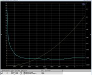
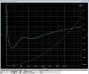
I am getting around 110dB SNR and around 0.002% distortion from 20 Hz up to 500 Hz.
At 500 Hz the problem starts. The distortion ramps up very quickly such that by 5 kHz the distortion is around 0.15%. This is very stark difference to 0.002%.
Long story short I am starting to suspect that the output filter that I am using is causing the distortion. I have gone over the modulator changing the filter corners and error amplifier / integrator gain. I have also tried multiple other op amps including the LM4562 and AD8620, But no matter what I do the ramp in distortion does not budge.
For this design it is my first time using this type of inductor: http://www.sagami-elec.co.jp/file/7G09B.pdf.
The filter capacitor is Film 150nF 100V: Panasonic / ECWU1154JC9
Output filter picture can be seen as attachment.
Does anybody here have experience with those Sagami inductors? Do they have problems at higher frequencies?
Maybe I am overlooking something else also. All comments are greatly appreciated.
I am lucky enough to have some very good audio test equipment at work namely the Audio Presicion ATS-2 and APx525.
The self-oscillating modulator is my own discrete design with a switching frequency varying from 400kHz to 700kHz. Opamps are OPA1612 and comparator is LT1711.
I am getting around 110dB SNR and around 0.002% distortion from 20 Hz up to 500 Hz.
At 500 Hz the problem starts. The distortion ramps up very quickly such that by 5 kHz the distortion is around 0.15%. This is very stark difference to 0.002%.
Long story short I am starting to suspect that the output filter that I am using is causing the distortion. I have gone over the modulator changing the filter corners and error amplifier / integrator gain. I have also tried multiple other op amps including the LM4562 and AD8620, But no matter what I do the ramp in distortion does not budge.
For this design it is my first time using this type of inductor: http://www.sagami-elec.co.jp/file/7G09B.pdf.
The filter capacitor is Film 150nF 100V: Panasonic / ECWU1154JC9
Output filter picture can be seen as attachment.
Does anybody here have experience with those Sagami inductors? Do they have problems at higher frequencies?
Maybe I am overlooking something else also. All comments are greatly appreciated.
Attachments
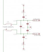
This appears to be a common mode inductor, do you have both windings phased correctly, the schematic makes it appear they are reversed one relative to the other.. (I am assuming a bridged output.)
It's been more than a decade since I last worked on a class D amp, but the bridged ones I worked with did not use CM chokes, but had an independent diff mode choke on each output of the pair. The output filter is an integrator and I suspect the choke may not have enough differential inductance to do the job, probably a very sizeable amount of HF current in the caps.
It's been more than a decade since I last worked on a class D amp, but the bridged ones I worked with did not use CM chokes, but had an independent diff mode choke on each output of the pair. The output filter is an integrator and I suspect the choke may not have enough differential inductance to do the job, probably a very sizeable amount of HF current in the caps.
This appears to be a common mode inductor, do you have both windings phased correctly, the schematic makes it appear they are reversed one relative to the other.. (I am assuming a bridged output.)
It's been more than a decade since I last worked on a class D amp, but the bridged ones I worked with did not use CM chokes, but had an independent diff mode choke on each output of the pair. The output filter is an integrator and I suspect the choke may not have enough differential inductance to do the job, probably a very sizeable amount of HF current in the caps.
My understanding was that even though it is a single part it is actually two individual inductors (not coupled). I will contact sagami to verify this.
Depending on the power level you're testing at this might be normal pre-filter feedback behaviour. Since you didn't post a THD versus power sweep for us to look at you might try comparing to, for example, figure 24 of the IRAUDAMP4A datasheet.
Depending on the power level you're testing at this might be normal pre-filter feedback behaviour. Since you didn't post a THD versus power sweep for us to look at you might try comparing to, for example, figure 24 of the IRAUDAMP4A datasheet.
I have both pre and post filter feedback. I will get these plots poster later today.
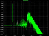
I have posted some plots that i did earlier today with the audio analyzer. They should be self explanatory I guess.
Attachments
-
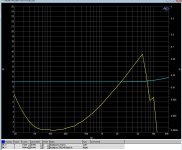
 Power_VS_THD+N@500Hz.jpg177.3 KB · Views: 52
 -
 Power_VS_THD+N@5kHz.jpg188.3 KB · Views: 53
 -
 HALF_Power_THD+N_VS_FREQ.jpg201.5 KB · Views: 538
 -
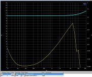 Full_Power_THD+N_VS_FREQ.jpg196.6 KB · Views: 70
 -
 FFT_IMD_80hz_&_3kHz.jpg223.9 KB · Views: 207
 -
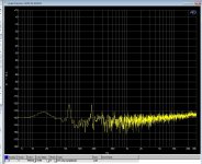 FFT_Idling_Zero_Input.jpg217.3 KB · Views: 208
 -
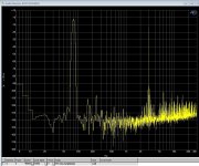
 FFT_500Hz_Full_Scale.jpg216.1 KB · Views: 212
 -
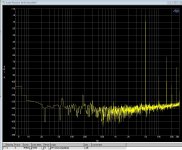 FFT_5kHz_Full_Scale.jpg209.4 KB · Views: 220
On a summary calculation, the cut-off frequency of your filter is about 90kHz - that's VERY high (especially for a self-oscillating amp). More common target frequencies are around half that.
2x 22uH + 330nF would put you around 42kHz.
2x 22uH + 330nF would put you around 42kHz.
Can you post a schematic too? Kinda hard to reason about this with only a partial schematic that's misleading for the parts of the design it does show.I have both pre and post filter feedback. I will get these plots poster later today.
Last edited:
Can you post a schematic too? Kinda hard to reason about this with only a partial schematic that's misleading for the parts of the design it does show.
Here is the schematic.
Attachments
Here is the schematic.
Some of the parts have been modified during testing, but it is pretty much the same schematic as you see there. There is also a lot more capacitance on the +12V and -12V rails that is now show.
In simulations using both tina-ti and ltspice I get around .005% to 0.008% distortion at 5kHz.
Well, that just says your simulation is wrong. 😉 I've found quite a bit of care is needed in TINA-TI's transient sim setup to get believable results above 0.1% THD, much less below 0.01%. Not really a bug per se, just the limitations of model accuracy and the available numerics. Also easy to hit grief with models connecting to node 0 internally and hence behaving improperly in dual supply sims.
Would you mind sharing your .tsc file? I'd like to look into what's happening with the feedback networks around the 1612s and that'd save me copying the schematic and pulling in the non-TI models. (You'll either have to change the extension to meet DIYA's attachment requirements or we can swap emails in PM.) With the supplies you're running the modulator has probably only a couple dB loop gain, suggesting either the 1612s are cancelling each other or ending up with effectively no loop gain due to clipping or the like occurring someplace within loop.
Something to try in the meantime would be to walk through nodes of interest with an oscope and simply watch what's going on. If you haven't already done that it might raise some new ideas for investigating. In particular I'd look at the drivers' floating supplies. VDDB to GND might be OK but the lack of a connection between VDDA and +12 makes me curious about what's happening with the high side switches.
Well, that just says your simulation is wrong. 😉 I've found quite a bit of care is needed in TINA-TI's transient sim setup to get believable results above 0.1% THD, much less below 0.01%. Not really a bug per se, just the limitations of model accuracy and the available numerics. Also easy to hit grief with models connecting to node 0 internally and hence behaving improperly in dual supply sims.
Would you mind sharing your .tsc file? I'd like to look into what's happening with the feedback networks around the 1612s and that'd save me copying the schematic and pulling in the non-TI models. (You'll either have to change the extension to meet DIYA's attachment requirements or we can swap emails in PM.) With the supplies you're running the modulator has probably only a couple dB loop gain, suggesting either the 1612s are cancelling each other or ending up with effectively no loop gain due to clipping or the like occurring someplace within loop.
Something to try in the meantime would be to walk through nodes of interest with an oscope and simply watch what's going on. If you haven't already done that it might raise some new ideas for investigating. In particular I'd look at the drivers' floating supplies. VDDB to GND might be OK but the lack of a connection between VDDA and +12 makes me curious about what's happening with the high side switches.
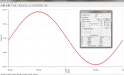
I have attached a simulation from ltspice in a zip file. I will attach the tina-ti file tomorrow. Attached is also a screenshot of the finished simulation.
You can see below. At 5kHz the THD is .0081%.
Harmonic Frequency Fourier Normalized Phase Normalized
Number [Hz] Component Component [degree] Phase [deg]
1 5.000e+03 1.814e+01 1.000e+00 -4.21° 0.00°
2 1.000e+04 5.892e-04 3.249e-05 86.36° 90.57°
3 1.500e+04 1.850e-04 1.020e-05 95.91° 100.13°
4 2.000e+04 6.064e-04 3.344e-05 83.57° 87.79°
5 2.500e+04 6.448e-04 3.555e-05 23.44° 27.65°
6 3.000e+04 5.718e-04 3.153e-05 74.63° 78.85°
7 3.500e+04 1.589e-04 8.761e-06 -35.88° -31.66°
8 4.000e+04 6.129e-04 3.380e-05 90.02° 94.24°
9 4.500e+04 5.297e-04 2.921e-05 43.46° 47.67°
Total Harmonic Distortion: 0.008129%
Attachments

I use separate t106-2 cores with as many turns as I can get on of 18SWG enamelled copper wire.
Where do you order/buy these?
Including the dead time configured on the SI8234s in the LTSpice model results in about half the measured distortion (results below). It's not immediately obvious to me what else is missing; looking at the measured spectra could be insightful.
I think the TINA model is insufficiently detailed to be meaningful.
Harmonic Frequency Fourier Normalized Phase Normalized
Number [Hz] Component Component [degree] Phase [deg]
1 5.000e+03 1.814e+01 1.000e+00 -4.22° 0.00°
2 1.000e+04 3.086e-03 1.702e-04 59.29° 63.51°
3 1.500e+04 6.328e-04 3.489e-05 97.41° 101.63°
4 2.000e+04 3.020e-03 1.665e-04 58.40° 62.62°
5 2.500e+04 1.062e-03 5.857e-05 64.47° 68.69°
6 3.000e+04 3.796e-03 2.093e-04 50.71° 54.92°
7 3.500e+04 1.488e-03 8.204e-05 102.57° 106.78°
8 4.000e+04 3.877e-03 2.138e-04 38.73° 42.94°
9 4.500e+04 2.869e-03 1.582e-04 96.93° 101.15°
Total Harmonic Distortion: 0.042728%
I think the TINA model is insufficiently detailed to be meaningful.
Number [Hz] Component Component [degree] Phase [deg]
1 5.000e+03 1.814e+01 1.000e+00 -4.22° 0.00°
2 1.000e+04 3.086e-03 1.702e-04 59.29° 63.51°
3 1.500e+04 6.328e-04 3.489e-05 97.41° 101.63°
4 2.000e+04 3.020e-03 1.665e-04 58.40° 62.62°
5 2.500e+04 1.062e-03 5.857e-05 64.47° 68.69°
6 3.000e+04 3.796e-03 2.093e-04 50.71° 54.92°
7 3.500e+04 1.488e-03 8.204e-05 102.57° 106.78°
8 4.000e+04 3.877e-03 2.138e-04 38.73° 42.94°
9 4.500e+04 2.869e-03 1.582e-04 96.93° 101.15°
Total Harmonic Distortion: 0.042728%
Attachments
Including the dead time configured on the SI8234s in the LTSpice model results in about half the measured distortion (results below). It's not immediately obvious to me what else is missing; looking at the measured spectra could be insightful.
I think the TINA model is insufficiently detailed to be meaningful.
Harmonic Frequency Fourier Normalized Phase Normalized
Number [Hz] Component Component [degree] Phase [deg]
1 5.000e+03 1.814e+01 1.000e+00 -4.22° 0.00°
2 1.000e+04 3.086e-03 1.702e-04 59.29° 63.51°
3 1.500e+04 6.328e-04 3.489e-05 97.41° 101.63°
4 2.000e+04 3.020e-03 1.665e-04 58.40° 62.62°
5 2.500e+04 1.062e-03 5.857e-05 64.47° 68.69°
6 3.000e+04 3.796e-03 2.093e-04 50.71° 54.92°
7 3.500e+04 1.488e-03 8.204e-05 102.57° 106.78°
8 4.000e+04 3.877e-03 2.138e-04 38.73° 42.94°
9 4.500e+04 2.869e-03 1.582e-04 96.93° 101.15°
Total Harmonic Distortion: 0.042728%
The LTspice simulation that I put up had the correct dead times to correspond with what is currently on the PCB. currently on the PCB the resistors that set the dead time are 2k, hence in the simulation the dead time was set to 20nS.
I got some Class-D toroidal filter inductions and I will try them out in the next few days. Hopefully this is where the issue was/is.
Last edited:
You seem to be confusing propagation delay with dead time. Might want to revisit that.hence in the simulation the dead time was set to 20nS
You seem to be confusing propagation delay with dead time. Might want to revisit that.
I know the difference between propagation delay and dead time. Maybe I am not understanding you.
Can you please post the simulation that you ran? Maybe you can also elaborate?
In the simulation that I posted B1 and B2 delay functions model the propogation delay of the SI8432. The capacitors C7 and C8 control the deadtime of the drivers. 20pF is 20nS.
An externally hosted image should be here but it was not working when we last tested it.
- Status
- Not open for further replies.
- Home
- Amplifiers
- Class D
- Distortion at frequencies above 500Hz???