OS, one problem with using hundred-watt drivers in an EF3 is that due to their large capacitance, if the amp oscillates, the predrivers will readily saturate into them. When this happens the predrivers act like rectifiers, pumping up output stage bias. I think this is very dangerous behavior.
One thing you could do to help with this is to give the predrivers at least 54mV of degeneration, this way they will never be more than 150% eager to drive the outputs, until rectification begins. This won't stop the rectifier action, but it should provide a degree of safety as long as oscillation is not severe. Adding reverse schottkeys across the emitters and degeneration will limit the predriver output current by overloading the VAS.
Just the act of oscillating is dangerous. 😱
Show examples....
PS - Cob of 15032/33 (15028/29 datasheet) is 200-500pf depending on (Vr).
Cob of NJWxxxx is a straight 400pF .... they seem very similar ??
This use of large drivers is common on commercial amps , where abuse and warranty
are the front issues. I have many schema's of these , no special additional circuitry ...
in fact some are "sloppy" , using just certain devices to ensure stability.
I'm open minded .. IF this would be an issue , a few sanken to-3P's are just 200p Cob
with 50 mhz Ft ... better yet !!
Wow !! sanken 2SA1186/2SC2837 has just 110pF cob ... MJE is "smacked down"
http://www.semicon.sanken-ele.co.jp/sk_content/2sa1186_ds_en.pdf
OS
Last edited:
Those are "smokin' good devices ... will get models. 🙂
OS
Yes, perfect input stage devices. And available at Mouser. 🙂
PS. It sounds insane but I'm going to try them as drivers. Distributed and cascoded.
I have some of those, with the old-style ceramic-like TO92 cases with silver print.
I remember starting to make models for them, but I couldn't find enough data. Looks like the datasheets will be good enough though, so I might try it.
I remember starting to make models for them, but I couldn't find enough data. Looks like the datasheets will be good enough though, so I might try it.
Just the act of oscillating is dangerous. 😱
Show examples....
PS - Cob of 15032/33 (15028/29 datasheet) is 200-500pf depending on (Vr).
Cob of NJWxxxx is a straight 400pF .... they seem very similar ??
This use of large drivers is common on commercial amps , where abuse and warranty
are the front issues. I have many schema's of these , no special additional circuitry ...
in fact some are "sloppy" , using just certain devices to ensure stability.
I'm open minded .. IF this would be an issue , a few sanken to-3P's are just 200p Cob
with 50 mhz Ft ... better yet !!
OS
Simulation shows progressive reponse peaking after each EF stage in the OPS, and this is causing a peak in the MHz region. If this is taken care of my simulation is stable. Try using Cordell's models, that's what I used.
Also, the C2911/A1209 models have bad Ft modeling, I wouldn't use them.
Another possibility is to use higher predrive bias; this makes the class AB driver region larger so they can drive more before beginning to rectify. But really, I don't see much of a reason this design should be at risk of oscillation. Still, it's possible strong RF noise on the input may cause predriver rectification, so I think this issue needs to be taken care of from multiple angles.
Fairchild have a KSA733 model. Can't figure out how to change the file extension to upload.
Copy/paste ??
OS
Member
Joined 2009
Paid Member
I´ve been doing similar kind of "rumble" with Dunlaps Krill ops and various different VGS:s. An interesting journey which will likely continue with new toys presented in this thread...
J
I've always liked the Dunlap Krill although never built one myself - please, even if a bit OT, can you tell me your experience with it (PM me if you wish).
Simulation shows progressive reponse peaking after each EF stage in the OPS, and this is causing a peak in the MHz region. If this is taken care of my simulation is stable. Try using Cordell's models, that's what I used.
If your models don't have Cbe, or it's too low, then your simulation may not show this effect. The OnSemi models are known for being inconsistent, which is why Cordell and Andy made custom models in the first place. Here is a collection of models vetted by me that are known to not have major quirks, except for saturation behavior which only very few models do right (and might not be possible to do right because of the simulator code). I rarely use any other models, because I know how bad they usually are. The vendor model libraries are convenient, but for me it's not fun anymore to use dubious models.
http://startfetch.com/keantoken/ltspice/kean4.bjt
Open it up in Notepad and read the beginning comments to understand it.
Eventually I may have a better solution:
http://www.diyaudio.com/forums/soft...pendent-simulations-diyaudio.html#post3835790
Thanks for that , Keen.
680R for the predriver (4ma instead of 2 ) also lowered THD.
I might even try 560/470R.
We are using to-126 - a little more Ic won't hurt.
OS
680R for the predriver (4ma instead of 2 ) also lowered THD.
I might even try 560/470R.
We are using to-126 - a little more Ic won't hurt.
OS
Thanks for that , Keen.
680R for the predriver (4ma instead of 2 ) also lowered THD.
I might even try 560/470R.
We are using to-126 - a little more Ic won't hurt.
OS
I use 680R. Because my first version PCB has an error (forget to connect one pattern 😱), I make again with several change on layout. Now the predriver has small heatsink. I already ordered to PCB maker because I do not have skill to iron PCB.
Anyway, PCB maker (home industries) is cheap here, you can order one piece PCB.The quality is good. They can make through hole double layer PCB. Although they claiming can make pattern as small as 0.2mm, I don't believe it, my minimum pattern is around 0.6mm (I use it for microcontroller application).
New models ....
Cut my "standard.bjt" from lib ...
Renamed "kean.bjt" -" standard.bjt" (in "lib" folder) ... away we go !
Everything seems to work the same with the better
models.
CFA's clip with the same tiny amount of saturation.
The "blameless" shows the same hideous saturation without
clamping.
THD is a little better and the simulator does not have to search
too long for operating points / (too many "fill ins ).
Nice collection of models for BJT amp design 😎 🙂 .
PS - sanyo models are a little "squirrley" - but work ?
OS
If you can notice anything strange with any of the models, then they are probably faulty, so don't hesitate to tell me when you can. I'm gradually refining it, so feedback helps. There might be a few models that slipped past me but they are largely vetted, so I'm pretty confident.
PS: That KSA733 model looks suspect. Irb is the point where Rb drops to half, but it's set at 1.5nA! That could be a way of leaving 150R base resistance (noise) in but making the simulation not show it; I'm starting to suspect fraud being the major reason for bad models.
PS: That KSA733 model looks suspect. Irb is the point where Rb drops to half, but it's set at 1.5nA! That could be a way of leaving 150R base resistance (noise) in but making the simulation not show it; I'm starting to suspect fraud being the major reason for bad models.
I'm starting to suspect fraud being the major reason for bad models.
But then... would that not bring forth lawsuits and erode confidence ?
Not to mention lost $$$ 😀 .
OS
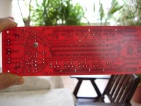
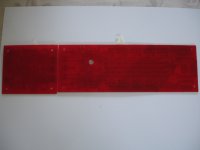
Hademade pcb as usual.
I want to start but i haven't many parts especially small signal transistors....
Ostripper what's your opinion for the possibility of use bc... series just for first try?
I want to start but i haven't many parts especially small signal transistors....
Ostripper what's your opinion for the possibility of use bc... series just for first try?
Attachments

Last edited:
But then... would that not bring forth lawsuits and erode confidence ?
Not to mention lost $$$ 😀 .
OS
Imagine how much money was payed to companies such as MODPEX to generate thousands of Spice models that are now known to be broken and almost useless. I'm sure that did produce some legal situation, even if we didn't hear about it. There is also this line in some model libraries:
The model is believed accurate but no condition or warranty as to its merchantability or fitness for purpose is given and no liability in respect of any use is accepted by <insert company here>
And, it DID erode confidence. Notice companies usually don't jump at producing models for general purpose and non-specialized parts. Simulation has such a stigma, much of it as a result of the terrible models, even though the simulator code itself works very well. People who are proficient with working with real circuits open simulation once, get some bogus result because of a ridiculous model, and give up instantly - because it's faster for them to build the circuit by hand than to wait out the learning curve of a simulator that requires days of research to use with reasonable accuracy.
We could do so much better, but those who have gotten past the learning curve always forget what it's like to be a new user, or if they do, they consider it someone else's problem. So no one is motivated to fix these issues.
At the same time, those with the level of education to code a simulator from the ground up are always closed off in corporate environments where they do what they're paid to do and nothing more, and are prevented with legal consequences for sharing their work.
Looks like a lot of work went into those models Keantoken. I'll give them a try. Thanks for sharing.
It was some work, but it was over a long period so it didn't feel like it so much. I began this maybe a year ago. In that sense maybe I was a bit lazy. But I DID produce in this case, so every bit counted. It's like donations. Whether a few people donate 25$, or loads of people donate 50 cents, it doesn't matter. The latter very often works better than the former.
Hademade pcb as usual.
I want to start but i haven't many parts especially small signal transistors....
Ostripper what's your opinion for the possibility of use bc... series just for first try?
Nice red pCB's !
BC can be used for the current mirrors (see just 12V vce ).
BCxxx you would have to reverse the device ,(and swap C/B around)
as BCxxx is a CBE pinout.
Most to-92's are ECB , the reason for my layout choice.
Input can also be BCxxx , provided the amp is powered by 50V rails.
You made the 5 pair version , so I assume you mant mega power !
BCxxx could 🙄 work (<50v rails) , but your application
(desire) seem to be for high power/high rails.
The to-126 BD139/140 are OK for the Cap multipliers (<60V rails), and
any Vbe (any rail V- they also "fit" - ECB).
Personally , unless it was the "baby" I was building ... stick to
the higher Vceo KSA/2SA -KSC/2SC devices ... they fit the layout and
are properly derated to ensure years of service.
OS
- Home
- Amplifiers
- Solid State
- Slewmaster - CFA vs. VFA "Rumble"