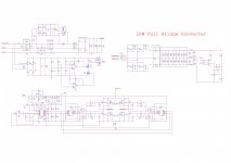
Hi guys, i have designed 2kW SMPS. Could you pls tell me whether this circuit has fault or not ? You can also give some advice to make it better. Thnx.
Attachments

Last edited:
I think with designs like these if your having to ask if there may be anything wrong with them you shouldn't be making them. There is huge potential consequences for something going wrong in high power SMPS or any mains SMPS for that matter.
I think with designs like these if your having to ask if there may be anything wrong with them you shouldn't be making them. There is huge potential consequences for something going wrong in high power SMPS or any mains SMPS for that matter.
There is no way to improve ourselves without taking any risk. Do you know any way without taking a risk ? I have just put it for professional designers. So i can learn my faults. I have designed 1kW SMPS before but ofc i couldnt have a chance for full test. I have put this in couple of forums but they all want to inform me about consequences. I know the consequences. Do not worry.
There is no way to improve ourselves without taking any risk. Do you know any way without taking a risk ? I have just put it for professional designers. So i can learn my faults. I have designed 1kW SMPS before but ofc i couldnt have a chance for full test. I have put this in couple of forums but they all want to inform me about consequences. I know the consequences. Do not worry.
Reading a book does not require one to undertake much risk.
Reading a book does not require one to undertake much risk.
Who said to you that i do not read a book ? I have calculated the all most everything from books. Pressman's book and power supply cookbook. Even if you read the all textbooks, you may not able to be successfull. Theory is not everything.
Okay so you designed this yourself - well done. If I was not sure about my design and felt the need to ask forum members I would not contemplate building it.
The reason I would not use forums as a mean to check your design is because in industry designs will be double and triple checked by other engineers and mistakes will still be made - it's just how things work. Asking a forum who you have no clue who are going to critique your work is scary for me especially when 350VDC is floating around.
The reason I would not use forums as a mean to check your design is because in industry designs will be double and triple checked by other engineers and mistakes will still be made - it's just how things work. Asking a forum who you have no clue who are going to critique your work is scary for me especially when 350VDC is floating around.
Okay so you designed this yourself - well done. If I was not sure about my design and felt the need to ask forum members I would not contemplate building it.
The reason I would not use forums as a mean to check your design is because in industry designs will be double and triple checked by other engineers and mistakes will still be made - it's just how things work. Asking a forum who you have no clue who are going to critique your work is scary for me especially when 350VDC is floating around.
I am asking because this is 2kW which is more powerful than 1kW i have designed before. Which part is floating ?😱
Fethiyeli, I have been studying SMPS for a few years and i think you are ahead of me in design. I can not say for sure you have anything wrong, but i can say you have many things right. Even if there is a mistake you did very good work.
A few minor things i see are no bleeder resistors on your 6800 uF input caps. And
no RC snubbers on your output diodes.
boscoe you are being very rude. Clearly Fethiyeli has a very good grasp on electronics and he does not deserve your condescending attitude.
A few minor things i see are no bleeder resistors on your 6800 uF input caps. And
no RC snubbers on your output diodes.
boscoe you are being very rude. Clearly Fethiyeli has a very good grasp on electronics and he does not deserve your condescending attitude.
Fethiyeli, I have been studying SMPS for a few years and i think you are ahead of me in design. I can not say for sure you have anything wrong, but i can say you have many things right. Even if there is a mistake you did very good work.
A few minor things i see are no bleeder resistors on your 6800 uF input caps. And
no RC snubbers on your output diodes.
boscoe you are being very rude. Clearly Fethiyeli has a very good grasp on electronics and he does not deserve your condescending attitude.
Thank you so much 😉 This is what i am looking for. I mean your comments really made me think again. I will add bleeder resistors for input caps and RC snubbers for output diodes.
As i said before, i have just put it to improve myself. I have been reading books but your comments are really more helpful than any book.
Thnx again.
Last edited:
SMPS design is pretty scary at times.
I remember some of my early designs exploding mosfets !!!
So I bought an isolation transformer and a variac.
I added a 0r1 resistor into the lower mosfet source so I can monitor current.
I powered up the SMPS IC off 12 volts then ramped up the variac slowly to see how much current was being taken. If it becomes too much then I switch off and work out why.
If the current is OK I can test regulation etc.
SMPS design is pretty scary at times.
I remember some of my early designs exploding mosfets !!!
So I bought an isolation transformer and a variac.
I added a 0r1 resistor into the lower mosfet source so I can monitor current.
I powered up the SMPS IC off 12 volts then ramped up the variac slowly to see how much current was being taken. If it becomes too much then I switch off and work out why.
If the current is OK I can test regulation etc.
No, It was fun to me. I remember connecting capacitors into wrong polarity voltage and dropping them under the table where the guy was working, trying to setup huge SMPS. I swear to God, I never felt such fun when these capacitors exploded and the guy was jumping like crazy,screaming -My God! What is now???
Yes, that was a time. Where did it go?
it's fun..but dangerous if someone near you has a heart problems 😛
i've been repaired my laptop SMPS and has been electrocuted by 420V and somehow i laughed even it's hurt 😛
and i appreciate to OP who brave enough to build an SMPS!.i wouldnt build something scary like this 😱
it's fun..but dangerous if someone near you has a heart problems 😛
i've been repaired my laptop SMPS and has been electrocuted by 420V and somehow i laughed even it's hurt 😛
and i appreciate to OP who brave enough to build an SMPS!.i wouldnt build something scary like this 😱
Have to admit. Was young and stupid=) But it was fun.
As i said before, no explosion no learning. Ofc, being electrocuted is wrong way to learn SMPS =) Thnx everyone.
fetiyeli, a design is much much more than a schematic. Asking people to review your 'design' is like saying have a look at my car I made, but just look at it from the outside.
Perhaps if you share with the forum your design document that describes why you chose the input and output levels, the topology, the main power conversion parts, the control scheme and feedback management, the hardware layout you intend to use, your loss calculations, your transformer design information, what emi specs you want to test to, what other output response performance you are aiming for, your methods for handling typical protection concerns, your cooling management. That type of info then allows us to view your design without having to design your amp ourselves in order to tell you how your design looks.
Perhaps if you share with the forum your design document that describes why you chose the input and output levels, the topology, the main power conversion parts, the control scheme and feedback management, the hardware layout you intend to use, your loss calculations, your transformer design information, what emi specs you want to test to, what other output response performance you are aiming for, your methods for handling typical protection concerns, your cooling management. That type of info then allows us to view your design without having to design your amp ourselves in order to tell you how your design looks.
fetiyeli, a design is much much more than a schematic. Asking people to review your 'design' is like saying have a look at my car I made, but just look at it from the outside.
Perhaps if you share with the forum your design document that describes why you chose the input and output levels, the topology, the main power conversion parts, the control scheme and feedback management, the hardware layout you intend to use, your loss calculations, your transformer design information, what emi specs you want to test to, what other output response performance you are aiming for, your methods for handling typical protection concerns, your cooling management. That type of info then allows us to view your design without having to design your amp ourselves in order to tell you how your design looks.
Hmm i see. You re right. All the calculations are in my notebook now. So many calculations but i will write here. Thnx.
why is bigger better
agree with trobbins RE schematic design without specifications is somewhat meaningless.
Personally I would rather see fethiyeli's 1KW design with actual hardware , It would be much more interesting to read a postmortem or lessons learned statement from your 1KW experience. Show us where you've been before, rather than a new design schematic simply doubling of power. Yer asking us to put work into reviewing your stuff without giving us anything in return.
Show a detailed empirical analysis of hard switching losses, IE prediction Vs measured. Is there a curve of hard switching switch losses Vs switching frequency ( exponential? ) that shows you can double power?
edit> I'd like to see what your 1 KW transformer looks like! windings build up / how many layers, creepage?
that would tell me a lot more about someone's SMPS experience.
Last edited:
why is bigger better
agree with trobbins RE schematic design without specifications is somewhat meaningless.
Personally I would rather see fethiyeli's 1KW design with actual hardware , It would be much more interesting to read a postmortem or lessons learned statement from your 1KW experience. Show us where you've been before, rather than a new design schematic simply doubling of power. Yer asking us to put work into reviewing your stuff without giving us anything in return.
Show a detailed empirical analysis of hard switching losses, IE prediction Vs measured. Is there a curve of hard switching switch losses Vs switching frequency ( exponential? ) that shows you can double power?
edit> I'd like to see what your 1 KW transformer looks like! windings build up / how many layers, creepage?
that would tell me a lot more about someone's SMPS experience.
Actually, ı didnt have a chance for testing my ex 1kW. My friend wanted me to design a 2kW SMPS so i designed it whether it is true design or not. I have informed my friend about that. I would like to share all of things such as waveforms, losses etc when you and other people did stop being arrogant.
A few more things.
I think the 50W bleeder is overkill. Personally i would use a load of 1 to 2W max per capacitor.
You should add a zener diode from the gate resistor to source to prevent false turn on. It goes between the controller and the gate drive resistor. Almost every ap not for a controller shows a zener there in at least one example.
Your current sense resistor is getting unreasonably large in wattage. Consider a current transformer or a LEM.
For the number of primary turns on your transformer you would need a switching freq around 50khz. You have 100khz now. With a full bridge the controller switching frequency is the transformer switching frequency.
What ohm load are you trying to drive at 2KW
- Status
- Not open for further replies.
- Home
- Amplifiers
- Power Supplies
- 2kW Full Bridge SMPS Design