A few more things.
I think the 50W bleeder is overkill. Personally i would use a load of 1 to 2W max per capacitor.
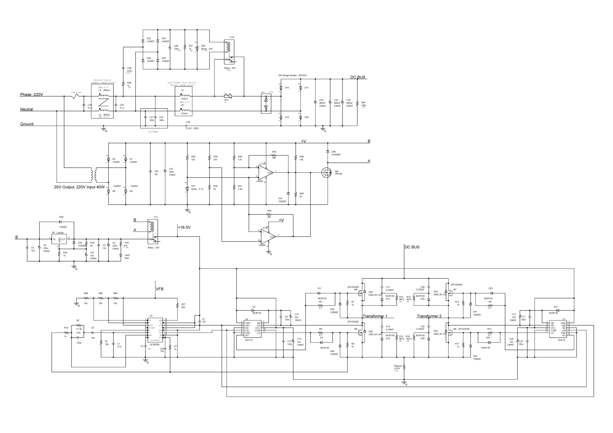
You should add a zener diode from the gate resistor to source to prevent false turn on. It goes between the controller and the gate drive resistor. Almost every ap not for a controller shows a zener there in at least one example.
Your current sense resistor is getting unreasonably large in wattage. Consider a current transformer or a LEM.
For the number of primary turns on your transformer you would need a switching freq around 50khz. You have 100khz now. With a full bridge the controller switching frequency is the transformer switching frequency.
What ohm load are you trying to drive at 2KW
Yea i can use 1W or 2W but in this case, discharge time will be much longer. Actually i dont know which discharge time is proper for discharging. I mean 342VDC must be discharged as soon as possible within certain power loss. I can put a lower value.
Does it have 100kHz ? ı thought switching frequency is half of the oscillator frequency. I have a application note of UC3825, in half bridge it has switching frequency which is half of the oscillator one.
Actually i have calculated transformer turns ratio by the textbooks but they all have different turns ratio. For example i have calculated it as 17:6, another one is 20:7, and final one is 15:4. I really dont know which one is correct. Because turns ratio also determines the flux in the core.
Yea i saw zener for gate of mosfet and i will add it now. I think i forgot to add it.
According to app note of UC3825, current sense resistor was calculated as 9.35W but i added 11W.
As i said before, i have designed it for my friend. I dont have any idea for now for driving 2kW.
Last edited:
I said 1 to 2W because I usually see 2W resistors on large electrolytics.
Half bridge and push pull is 1/2 controller frequency and full bridge is same frequency as controller. You should change your controller frequency to 50khz.
At 1600 Gauss a conservative value for older ferrites you would have 20 pri turns at 50 khz.
you have 17 pri turns, so you are around 1900 Gauss. A conservative number if you are using a modern ferrite.
I said 1 to 2W because I usually see 2W resistors on large electrolytics.
Half bridge and push pull is 1/2 controller frequency and full bridge is same frequency as controller. You should change your controller frequency to 50khz.
At 1600 Gauss a conservative value for older ferrites you would have 20 pri turns at 50 khz.
you have 17 pri turns, so you are around 1900 Gauss. A conservative number if you are using a modern ferrite.
In another forum, people said that only the push pull has a half of switching frequency of its oscillator frequency.
I couldnt see anything in textbooks about that topic. I mean switching vs oscillator frequency.
Ok ths answer a bit off topic but i think the actual question is is this post appropriate for this DIY forum.
Most answer you got here are in the domain of the epistemological justification for believing this SMPS will work.
Mains power is as dangerous as it gets and 2kw is as large as power supplies gets so its eas to understand the alarm of some contributors, as this is on the extreme side of being dangerous and definitely pro's territory.
I think that's why Boscoe was harsh, I don't think he tried to be condescending.
To understand your design and choices you made in it' other people need to understand what is you background i designing, building and testing these. If certain decisions where made based on your theoretical understanding or practical experience and what these are. To trust people's opinion you need to weight them according to what you know about their knowledge and background, and can you know enough considering ths is an internet forum and the topic is big a** power supply ? 🙂
cheers
Perhaps the OP's initial request could have been approached better, and perhaps he has actually put in a lot of design effort, and perhaps he has a fair background in electrical circuits but not specifically switchmode. Perhaps let's not shoot from the hip until we ask the OP to present more design details, or for the OP to maybe just focus on one design aspect at a time - which may then be of more interest to everyone. And to be fair, the OP hasn't indicated if the circuit is anything more than a design exercise, in which case his prowess and experience in testing, and the issue of hazards and standards compliance wouldn't arise.
The OP wouldn't be the first designer to copy/paste direct from device app sheets, but maybe he has tweaked something for a reason that could be elaborated on.
The OP wouldn't be the first designer to copy/paste direct from device app sheets, but maybe he has tweaked something for a reason that could be elaborated on.
I am pretty sure the OP hasn't built/tested too much.
using a pri. current sense resistor in a 1KW SMPS tells me all I need to know.
I gave up on a 300W forward current mode job, ie accuracy and sense noise.
trobbins gives him too much credit this far into this thread.
I don't mind helping a fella learn , but sheesh were bordering into fantasy territory.
Last edited:
Actually, ı didnt have a chance for testing my ex 1kW.
but it is built and working now ?
I suppose its for disco PA ?
why go from 1KW to 2KW without testing the 1KW properly ?
trobbins gives him too much credit this far into this thread.
I don't mind helping a fella learn , but sheesh were bordering into fantasy territory.
The OP has made few clarifications on this thread, probably due to a poor handle on English and having severely bashed ears from people making inane assumptions from scant OP info. But the bashing just keeps coming "this far in to the thread" (as if the thread has timeline restrictions on responses akin to a pro game of chess).
Last edited:
but it is built and working now ?
I suppose its for disco PA ?
why go from 1KW to 2KW without testing the 1KW properly ?
My friend just wanted me to design this SMPS. I've been reading textbooks about power electronics but i dont know whether my background is enough or not.
My ex SMPS was working properly but as i said before, i didnt have chance for full test.
and now i see that i think i will never share anything in this forum.
The OP has made few clarifications on this thread, probably due to a poor handle on English and having severely bashed ears from people making inane assumptions from scant OP info. But the bashing just keeps coming "this far in to the thread" (as if the thread has timeline restrictions on responses akin to a pro game of chess).
if anyone's shooting from the hip... it be contained above
I can assure you designing 1KW SMPS is not a game.
discussing vaporware for some folks is.
We're on a diy forum. Posters don't get credibility rankings based on a poll of the swarm that is viewing a thread, or some minimum number of approved posts that gains them a 'competent' person status for presenting designs. Anyone posting makes up there own mind as to whether they want to contribute to the technical discussion, or to advise if a person is showing a shortfall in competency on some aspect, whether that be burning themselves soldering, or able to stick probes in and make a voltage measurement, or wiring in a fuse or isolation transformer, or fixing up some failed equipment only to then sell it or pass it on to a friend. I made up my mind not to technically contribute, but I didn't hit the OP over the head for asking.
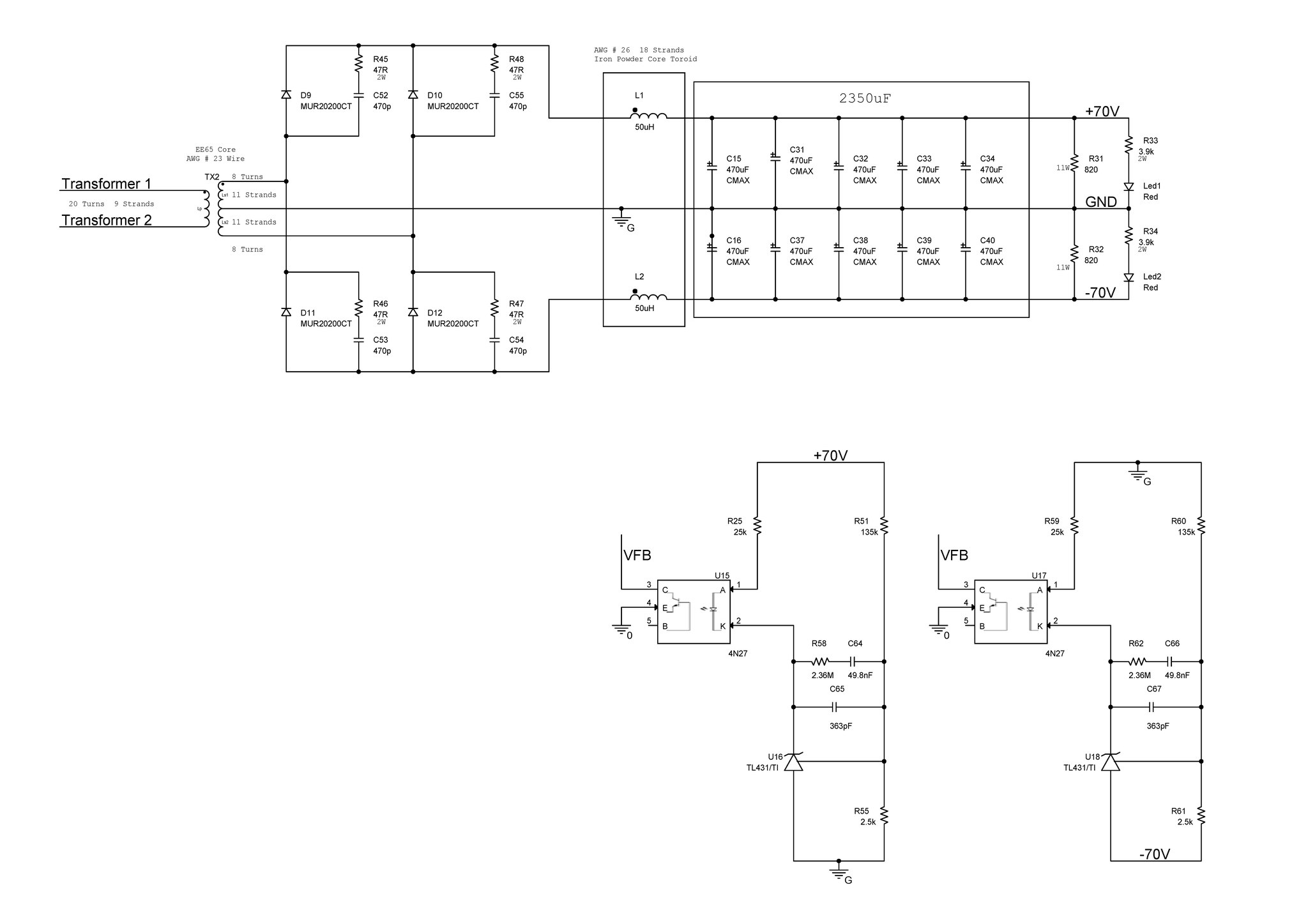

Do you think this feedback network is correct ? As i know, the aim is to share feedback currents and i did it but i dont know whether it is correct or not.
This is the final schematic for now.
An externally hosted image should be here but it was not working when we last tested it.
An externally hosted image should be here but it was not working when we last tested it.
- Status
- Not open for further replies.
- Home
- Amplifiers
- Power Supplies
- 2kW Full Bridge SMPS Design