3EF Response against Source Resistance
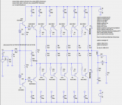
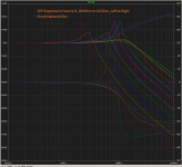
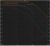
I did a few plots recently trying to get a feel of the temper of 3EF. The result seems to be that they like low-Z sources at high frequencies for good stability. If low-Z is not possible, a shunt network can help. These plots made sense to me as for why using and tweaking the bypass cap on a VAS degeneration resistor contributed to gain margin.
I did a few plots recently trying to get a feel of the temper of 3EF. The result seems to be that they like low-Z sources at high frequencies for good stability. If low-Z is not possible, a shunt network can help. These plots made sense to me as for why using and tweaking the bypass cap on a VAS degeneration resistor contributed to gain margin.
Attachments
Last edited:
Confirmed ... this triple can be very stable without the 33p B-C shunts while
simulating a CFA IPS. Hook up a "blameless" , and SW tests will show VERY
HF ringing.
I would suggest leaving the 2 33pF's alone , as one might want to use
many IPS's. Better safe than sorry ...
PS - It could also be a symmetrical/asymmetrical phenomena ... H/K's
990 has no shunts but has ferrite beads and inductors on the
output stage devices.
Edit - Actually , looking more closely ... they shunt with 270p at the VAS.
OS
Its exactly what Self says, use a little shunt when using triple output stage with VFAs. This is in his new book as in the previous book he doesnt recommend the use of triples because of stability issues. After some experimentation he has now found the mechanism to resolve the stability issues. He is a little late though, this has been known by many commercial designers for at least 30 years.
I did a few plots recently trying to get a feel of the temper of 3EF. The result seems to be that they like low-Z sources at high frequencies for good stability. If low-Z is not possible, a shunt network can help. These plots made sense to me as of why using and tweaking the bypass cap on a VAS degeneration resistor contributed to gain margin.
Thats it 😉, youll also notice that you can push ULGF higher.
Thanks for that.
I'll need to do some sim work to understand it better.
When you say shunt, I am assuming you mean a cap from the TIS output to GND?
I made some simulation, and I have built some version of that. I have never find any oscillation until now.
I put some results in the CFA topic.
Sajti
Edit - Actually , looking more closely ... they shunt with 270p at the VAS.
OS
I like much better this shunt solution. You need only one capacitor to define the dominant pole. This can be a good quality one.
Another issue that the ground usually "cleaner", comparing to the HT, so compensating to ground can gives less noise.
Sajti
I sim, CFA using Hawksford cascode on VAS, the result slew rate is suffer , especially negative slew rate. Only 60-70V/uS on negative slew rate. But when I use standard VAS like VSSA (Lazy Cat) or NX Amp (Bonsai), I have high slew rate, much more higher than Hawksford cascode and positive - negative slew rate is symmetrical. Why?
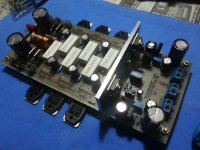
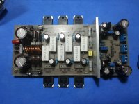
Hello Os, my progres so far ...
Only need to solder output transistor and bias spreader to heatsink.
I'll need your guide for first power up and setup my Slewmaster when it ready.
Thank you
Naf
Only need to solder output transistor and bias spreader to heatsink.
I'll need your guide for first power up and setup my Slewmaster when it ready.
Thank you
Naf
Attachments

Hello Os, my progres so far ...
Only need to solder output transistor and bias spreader to heatsink.
I'll need your guide for first power up and setup my Slewmaster when it ready.
Thank you
Naf
It look good.
thank you mas BimoIt look good.
yes it look cool, a true Do it Myself 🙂
Hello Os, my progres so far ...
Only need to solder output transistor and bias spreader to heatsink.
I'll need your guide for first power up and setup my Slewmaster when it ready.
Thank you
Naf
😎🙂
Are there any others who have built or almost finished? And, can test data be soon appearing?
Thx-RNMarsh
Ostripper, my version of 3EF board is likely over compensated a bit. When heat sink getting warm, the bias current fall.
Last edited:
Ostripper, my version of 3EF board is likely over compensated a bit. When heat sink getting warm, the bias current fall.
YES ! EF3 "slewmaster" is the same as the H/K 680r ... except for the NJWxxxx
drivers.
I anticipated this. There are two ways to compensate for this.
-Lower the Hfe of the vbe's ... (use mje 340's) is one way.
-The other way is to change R103 on the dual Vbe circuit , try 2.2k or 1.5K
here to change the coefficient .
Keep in mind that the OPS has to run awhile (at a moderate bias) to stabilize. If you make either of
my 2 changes , allow at least 5-10 minutes (stabilization)to access the merit of the change.
At least we are overcompensated !! 🙂 (no runaway)
OS
Last edited:
I sim, CFA using Hawksford cascode on VAS, the result slew rate is suffer , especially negative slew rate. Only 60-70V/uS on negative slew rate. But when I use standard VAS like VSSA (Lazy Cat) or NX Amp (Bonsai), I have high slew rate, much more higher than Hawksford cascode and positive - negative slew rate is symmetrical. Why?
That would depend on your models or other unknowns ??
I got the CFA "record" with the UV LED hawksford/NX (500v/us ++) !!!
PS - that is why I made this my first IPS for the slewmaster - it "rocks" !!
OS
That would depend on your models or other unknowns ??
I got the CFA "record" with the UV LED hawksford/NX (500v/us ++) !!!
PS - that is why I made this my first IPS for the slewmaster - it "rocks" !!
OS
Dadod suggest to me to change KSC1845/KSA992 model to his model of Q2sc2240 and Q2sa970. The THD is lower and slew rate is higher. The slew rate is almost symmetric. May be KSC1845/KSA992 model is bad.
YES ! EF3 "slewmaster" is the same as the H/K 680r ... except for the NJWxxxx
drivers.
I anticipated this. There are two ways to compensate for this.
-Lower the Hfe of the vbe's ... (use mje 340's) is one way.
-The other way is to change R103 on the dual Vbe circuit , try 2.2k or 1.5K
here to change the coefficient .
Keep in mind that the OPS has to run awhile (at a moderate bias) to stabilize. If you make either of
my 2 changes , allow at least 5-10 minutes (stabilization)to access the merit of the change.
At least we are overcompensated !! 🙂 (no runaway)
OS
If heat sink at room temperature, the bias current fall fast. But after the heat sink get warm about 20 minutes, the fall is slow down. I adjust bias current again, but still it reduce slowly.
It might be good for first time experiment 😀 which it did not go to thermal runway. After experiment with my IPS, I will tweak the bias compensation.
First try VFA with Ostripper 3EF OPS.
Right now I listening in mono my VFA with Ostripper 3EF OPS. This is my first amp design using LTspice. Thank you for Ostripper with his idea of modular 3EF OPS. My version of 3EF OPS is a bit different from the original design from Ostripper. I using MJE15032 and MJE15033 for driver. And because KSC3503 and KSA1318 is difficult to find I use 2SC3423 and 2SA1360 for pre-driver.
Also thank you for Dadod and Bonsai who help me to use LTspice.
My VFA is LTP with EFA current mirror and VAS using Hawksford cascode. Compensation using TMC. With no input there is a litte noise when I put my ear few cm in front speaker. My VSSA variant is dead silent, my be I mess up with ground some where 😱.
With input sine signal there no indication of distortion (I hope, I can buy a distortion meter) on scope. With 25 kHz square signal, it is also perfect and no phase shift. (Next time I will build signal high frequency square wave signal generator).
First listening impression. More dynamic than my VSSA variant. Yes! Bass is little better than my VSSA variant. Detail in high frequency is about same, but my VSSA variant is more easy listening. May be I must tweak it some where.
Next time, I try my CFA with 3EF OPS.
To design audio amp for just working is easy task. I proud to my self 😀. But design audio amp for easy listening and not fatigue is another things.
Last edited:
Dadod suggest to me to change KSC1845/KSA992 model to his model of Q2sc2240 and Q2sa970. The THD is lower and slew rate is higher. The slew rate is almost symmetric. May be KSC1845/KSA992 model is bad.
Maybe Im missing something but what is the purpose of changing a model in a sim to be able to obtain better THD specs. What is important is what THD you obtain with what you actually built.
Most models are flawed, you should first verify the model against the datasheet info. Spice itself models the early voltage incorrectly for one, so its also flawed. Also keep in mind that the transistors that you are going to buy may have some normal parameter variances compared to the datasheet due to manufacturing variances.
How do you know the q2sc2240 model isnt flawed instead and showing better but false results.
Simulation only guide before we implement to real things. Of course we must verify it with some measurement. I was an engineer but not an audio engineer. I know how to design something 😀.
Every part may have different characteristics even if they produce at same lot. We must try worse case scenario, if there are some critical aspect we must ensure to use parts with more high precision, etc.
I just learn how to use LTspice, if I have time I will check the models and compare to the datasheets. Usually I use models from Bob Cordell. I do not know if the q2sc2240 bad or good, but I believe Dadod, he used q2sc2240 model for his amp, and work well in real amp. I need quick solution, so I use his models. If you think you have better model, please share it.
At least, I prove my amp is working and have good response for 25kHz square wave, no ringing, no overshoot, no phase shift.
If I have distortion meter, I will check it.
Here are a bunch of models I've collected (some I created) that I've tested and know to be accurate (except for quasi-saturation which is only included in the top-line models). I highly emphasize hand-made models, and all of the suffixed ones are.
If you have a model for a transistor that's not in this file, it's very highly likely that your model is faulty. It's better to try and find an alternative for it in these verified models.
If you have a model for a transistor that's not in this file, it's very highly likely that your model is faulty. It's better to try and find an alternative for it in these verified models.
Attachments
YES !!!
Slewmaster EF3 OPS is what I wanted to get built first.Thank you Bimo !
The IPS's , as they are interchangable... can be tweaked as desired.
Now that I know the OPS is good , I'll make more IPS's ... 😎
PS- I have 2 - 1 simple "symasym" variant and a " VSSA" variant ...
both are 20-30ppm thd20 and 90db PSRR ...
OS
- Home
- Amplifiers
- Solid State
- Slewmaster - CFA vs. VFA "Rumble"