your right hand graph (post #300) shows > 10dB attenuation on the tweeter. Most tweeters are at best 3dB more efficient, then accounting for bafflestep, max 9dB (usually less) attenuation requried. Less for a 3 way. which post contains raw driver measurements of all your chosen drivers? Did you take the measurements of each driver without changing mic gain, position etc...?
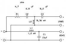
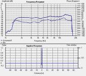
Yes I see the difference. No post with drivers measurements, I started now to measure. Measurements taken without any change: only with & without filter. Attached filter used.
Attachments
Last edited:
If Merlin and myself are doing it wrong, so is B&W.
I'm sorry, you've completely lost me here - what does B&W have to do with anything? Are you referring to their methodology or their use of drivers and xo's? Certainly I don't see them using either the 18W8545K0 nor the Seas T25CF002 so you must be referring to the trial-and-error-and-measure-and-listen xo implementation process you are employing here. Nothing wrong with that and B&W certainly uses it along with every other speaker company out there (I would hope), but if you think B&W isn't using software to get themselves into the ballpark to begin with then you are sadly mistaken.
3mH is a value which one does not want to use around 2,5 kHz
in our case. It's a fact.
No offense intended but I hate to be the one to tell you this but stating that something is a fact doesn't make it so.
Firstly, in my simulation, the xo was not at 2.5kHz - it was at about 2.2kHz. And clearly, the sim does show that it will work just fine with an inductor value that is above 3mH if the baffle step loss is about 6dB. Now that is a fact.
But don't take my word for it, let's look at how it doesn't work for other designs as well. Like here in this design with another 7" ScanSpeak driver, the 18W8531G Revelator: Speaker Design Works. The designer must have made a horrible mistake there - 3mH and a xo at 2200 Hz. OMG! I wouldn't even want to get near to listening to that. 🙄
Or perhaps Vance Dickason, the most respected speaker textbook author around (that's of the Loudspeaker Design Cookbook btw) and his LDC6 Studio Monitor that I mentioned previously has got it all wrong as well. This one actually does use the Scan 18W8545K0 but with the Scan D2905 tweeter. See the xo below and wow! - again a 3mH inductor on the woofer and the xo just below 2000Hz. That's way too far away from the 2200Hz that I used to be of any possible use to merlin. These guys must be out to lunch. (Very strange how similar that is to what I came up with, hmmmm....)
Now that some facts have really been established, I apologize for the interruption and my sarcastic tone. Certainly the process of trying different xo components and measuring is going to be helpful to merlin.
Carry on......
Attachments
Merlin, you're killing me. I thought you would be done with it by now
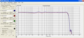
and you made just one measurement. Where is the woofer's response ?
Make a new measurement of the woofer and keep it in the display
There is this function of assigning each response a different color
and you can make them appear and dissapear in the display by
placing a checkmark.Object A has its own measure button .
Object B has its own measure button. If you choose A to be
a woofer, then the B can be tweeter. Uncheck the phase, it's
just making it harder to look at FR.
Attachments
I'm sorry, you've completely lost me here
I can't believe what i've just read. EOD
Last edited:

merlin - which post contains the raw (in box) driver measurements? what drivers are you using?
Tweeter Seas Excel Millennium & Woofer ScanSpeak 8545, attached both data sheets.
Attachments
Merlin,
EOD means end of discussion. I will make a final suggestion
which concerns only you because I engaged myself in this thread
just to help you and not waste my energy over nothing talking
to somebody else explaining my reasoning.
I will send you a private message through diyAudio interface
and work with you on your 2 way project until it is finished,
if you agree to that. I mean private as to stay private. I will not
post in this thread anymore.This is my final decision and I won't
change my mind.
merlin - which post contains the raw (in box) driver measurements? what drivers are you using?
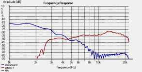
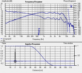
Attached drivers in box measurements without xover.
Attachments
Merlin,
EOD means end of discussion. I will make a final suggestion
which concerns only you because I engaged myself in this thread
just to help you and not waste my energy over nothing talking
to somebody else explaining my reasoning.
I will send you a private message through diyAudio interface
and work with you on your 2 way project until it is finished,
if you agree to that. I mean private as to stay private. I will not
post in this thread anymore.This is my final decision and I won't
change my mind.
Lojzek,
I'm sorry to hear you don't post anymore in my thread because the help I received can't help other people.
I haven't got received your private message.
Attached drivers in box measurements without xover.
Thanks - some observations...
The relative levels of the tweeter and woofer (in box without xovers) shows the woofer to be more sensitive than the tweeter. your raw measurements are suspect. Are you sure you measured both drivers without changing any mic gain or output volume between measurements?
Are you going for a 2 way or 3 way? this is very important since the size of the baffle will change (assuming you go for a 10" or larger diameter driver which I am assuming will play frequencies above 100Hz therefore directional therefore should be on the front baffle with the other drivers) - where less bafflestep compensation is required.
If you are going for a 2 way and require near full bafflestep compensation (eg >= 4dB) then your final system sensitivity will end up being 82dB. (since the woofer looks to me to be a nominal 86dB efficient driver after the bafflestep frequency based on the Scanspeak IEC baffle FR graph). This means you are going to need to apply around 6 - 8dB of tweeter attenuation. The absolute dB doesn't matter - it is the relativity and I'm getting this from the manufacturer graphs since I can't trust the ones you posted (since the woofer level looks higher than the tweeter as stated above).
It would be good if you can increase your gate (to get down to 200Hz), or at least get a nearfield measurement and try to splice to at least see the full baffle effect (to suitably target the amount and slope of bafflestep compensation required).
Lastly - have you found other designs with this popular combination of drivers? What slopes did they target and bafflestep comp given baffle geometry?
Correction: My above doesn't account for room gain at lower frequencies, therefore also affects absolute amount of bafflestep required. but I still reckon a 82 - 85dB sensitive system is your target
Last edited:
simulation is your friend 🙂
here are some factors that needed to be consider:
1. Acoustic Offset between T and M
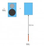
2. Mic distance should be at least 2x of baffle width to capture baffle step
3. If 3way you will need to combined the midwoofer measurements from nearfield (1-2cm from dustcap) and farfield (No. 2)
4. Impedance plot is necessary for crossover design.
5. Minimum phase response for both midwoofer and tweeter to get a good phase tracking between drivers.
6. Use Tweeter Vertical axis for your design, unless you are planning to sit well under the tweeter.
if you need more help to setup the proper measurements, let me know.
here are some factors that needed to be consider:
1. Acoustic Offset between T and M
2. Mic distance should be at least 2x of baffle width to capture baffle step
3. If 3way you will need to combined the midwoofer measurements from nearfield (1-2cm from dustcap) and farfield (No. 2)
4. Impedance plot is necessary for crossover design.
5. Minimum phase response for both midwoofer and tweeter to get a good phase tracking between drivers.
6. Use Tweeter Vertical axis for your design, unless you are planning to sit well under the tweeter.
if you need more help to setup the proper measurements, let me know.
simulation is your friend 🙂
here are some factors that needed to be consider:
1. Acoustic Offset between T and M
2. Mic distance should be at least 2x of baffle width to capture baffle step
3. If 3way you will need to combined the midwoofer measurements from nearfield (1-2cm from dustcap) and farfield (No. 2)
4. Impedance plot is necessary for crossover design.
5. Minimum phase response for both midwoofer and tweeter to get a good phase tracking between drivers.
6. Use Tweeter Vertical axis for your design, unless you are planning to sit well under the tweeter.
if you need more help to setup the proper measurements, let me know.
1. I don't know.
2. Mic distance is OK, is more than 2x baffle width
3. At this moment I want to optimize the 2 way xover
4. How to do it?
5. How to get the minimum phase reponse
6. OK
Thanks - some observations...
The relative levels of the tweeter and woofer (in box without xovers) shows the woofer to be more sensitive than the tweeter. your raw measurements are suspect. Are you sure you measured both drivers without changing any mic gain or output volume between measurements?
Yes
Are you going for a 2 way or 3 way? this is very important since the size of the baffle will change (assuming you go for a 10" or larger diameter driver which I am assuming will play frequencies above 100Hz therefore directional therefore should be on the front baffle with the other drivers) - where less bafflestep compensation is required.
At the moment 2 way
If you are going for a 2 way and require near full bafflestep compensation (eg >= 4dB) then your final system sensitivity will end up being 82dB. (since the woofer looks to me to be a nominal 86dB efficient driver after the bafflestep frequency based on the Scanspeak IEC baffle FR graph). This means you are going to need to apply around 6 - 8dB of tweeter attenuation. The absolute dB doesn't matter - it is the relativity and I'm getting this from the manufacturer graphs since I can't trust the ones you posted (since the woofer level looks higher than the tweeter as stated above).
It would be good if you can increase your gate (to get down to 200Hz), or at least get a nearfield measurement and try to splice to at least see the full baffle effect (to suitably target the amount and slope of bafflestep compensation required).
wich graph?
Lastly - have you found other designs with this popular combination of drivers? What slopes did they target and bafflestep comp given baffle geometry?
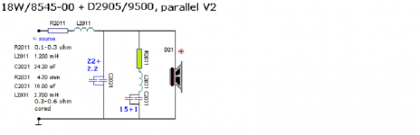
Attached schematic for SS 8545 designed by Troels Gravesen & Froy filter for tweeter designed by Seas
Correction: My above doesn't account for room gain at lower frequencies, therefore also affects absolute amount of bafflestep required. but I still reckon a 82 - 85dB sensitive system is your target
Attachments
Last edited:
how to determined acoustic offset
1. set the mic @80cm @tw axis
2. set your volume/pre around 75-85db reading from your tweeter
3. dont change the above, keep the mic at the same place, keep the volume at same position throughout the measurements.
4. measure your tweeter
5. measure your midwoofer
6. connect the T and M parallel and measure the MT response.
now, im not familiar with other xover simulation, i have been using jeff b's Passive Crossover Designer 7 with great success, it needs MS Excel 2007.
in PCD7, load the Woofer and Tweeter FRD, then import the MT measurements with the import overlay option just under the FR plot.
set the listening distance 0.8 on PCD, then input your physical vertical offset, if your midwoofer is below your tweeter with distance about 14cm, then put 0.14 as the units in meter.
play the Z-offset (Acoustic Offset) until you can match the summed MT frd with the overlay combined FRD.
typical Z-offset of 4-6" midwoofer to a dome tweeter is about 0.019-0.027.
- Status
- Not open for further replies.
- Home
- Loudspeakers
- Multi-Way
- Help for 3 or 4 way loudspeaker