I do not knopw if it works.
The transdiodes are supplied with constant current sources so they should not distort. Anyway, i found it interesting.
To ramp up the idle low value resistors in series with the transdiodes may be the best solution.
The transdiodes are supplied with constant current sources so they should not distort. Anyway, i found it interesting.
To ramp up the idle low value resistors in series with the transdiodes may be the best solution.
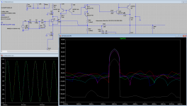
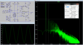
This is the circuit from #288, bias 10mA to 1.2A 🙂 as you can see (until 1.2A is set) there is not much difference in the FFT for the set idle current. This is all at 1Vin and 20Khz giving 5.5Watt out (very modest power setting). The picture shows the 2nd harmonic (and it is huge IMO).
Attachments
So it sounds like a tube, ehhh....
I am surpised. I expected much less distortion and a wider spread of harmonics.
What was the load in your simulation, 8 Ohm ?
I am surpised. I expected much less distortion and a wider spread of harmonics.
What was the load in your simulation, 8 Ohm ?
So it sounds like a tube, ehhh....
I am surpised. I expected much less distortion and a wider spread of harmonics.
What was the load in your simulation, 8 Ohm ?
I am surpised. I expected much less distortion and a wider spread of harmonics.
What was the load in your simulation, 8 Ohm ?
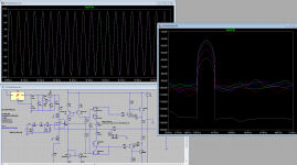
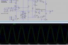
How does it look at 1kHz ?
1K 5.5Watt 8Ohm
Attachments
So there is no real benefit using the "improved" bias generator.
Using only the series resistors, what was the value you used to get 100mA idle ?
Using only the series resistors, what was the value you used to get 100mA idle ?

With resistors ranging from 100 to 150 ohm I get idle around 500mA but strangely the current is not the same on both emitter resistors r16 and r17
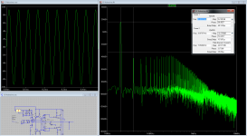
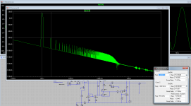
Keep the resistors around the bias generator (and the capacitor) it makes for a nice symmetrical drive. I made some changes to the PSU's and added a CCS to feed the mirrors, the 20K 5.5W FFT looks better 70dB now. I also added new D45 and D44 models. idle set to 100mA. More work to be done... 🙂 can you see it?
Attachments
Wow !!! That is a huge improvement.
That´s what i say, Frans is the Poweramp and PSU Guru.
Kudos Titan Gold.
That´s what i say, Frans is the Poweramp and PSU Guru.
Kudos Titan Gold.
Now we are talking 🙂🙂🙂
I am glad we finally got your attention.
I will now start to build the addons....
I am glad we finally got your attention.
I will now start to build the addons....
Now we are talking 🙂🙂🙂
I am glad we finally got your attention.
I will now start to build the addons....
Be warned 🙂 the PSU is 35+35V = 70V 😀 the BC546/556 are 65V this is borderline. Drop the PSU to 25+25V the amount of power will be the same (and I think) it also makes no difference on the FFT.
P.s. I just checked, 25+25V is fine, the bias resistor should be 150 Ohm.
Last edited:
We do not let you in the dark, never.
It is just that Frans and i are so busy in the survival game.
At least i can say that about me.
Lots of complicated work to do and High End Audio is not what it was 20 years ago.
Today it is all about the marketing and politics, success not guaranteed with so many choices.
I wish i had more time for this.
It is fun and rewarding.
When we have finished this, i will build the resulting circuit too.
We do not let you in the dark, never.
It is just that Frans and i are so busy in the survival game.
At least i can say that about me.
Lots of complicated work to do and High End Audio is not what it was 20 years ago.
Today it is all about the marketing and politics, success not guaranteed with so many choices.
I wish i had more time for this.
It is fun and rewarding.
When we have finished this, i will build the resulting circuit too.
What can I say 🙂 Titans always concur
I must say there are some compromises here..... difficult to use use another psu... can I keep the lovely 103 +-35v psu ?
Can I use other trannies (other than BC546/556) ?
Can I use other trannies (other than BC546/556) ?
We do not let you in the dark, never.
It is just that Frans and i are so busy in the survival game.
At least i can say that about me.
Lots of complicated work to do and High End Audio is not what it was 20 years ago.
Today it is all about the marketing and politics, success not guaranteed with so many choices.
I wish i had more time for this.
It is fun and rewarding.
When we have finished this, i will build the resulting circuit too.
Way cool......
You know, I am not a very good simulator and or designer, but fortunately I have golden ears and can build stuff.... done that been there 🙂
- Status
- Not open for further replies.
- Home
- Source & Line
- Analogue Source
- JG´s Nobrainer and Nobrainer Discrete