Thanks Bob! As with everything diy, the more that is revealed the more I realise how little I actually know!! 🙂
Also above I forgot to multiply my current by amps for my watts... it should have been 25W class A when I said 10W and here was I thinking only 10W! 🙄
Also I've realized that I do need a bigger transformer if I want to drive 4 ohm loads 🙄 the guidelines would have been on the assumption of 8 ohm loads... If I want a hope of delivering the extra current that a 4ohm load can demand then I really need to double the transformers capacity. doh.
Tony.
The transformer for a ClassA amplifier is usually specified as 6times to 10times the maximum ClassA output.
Your 25W ClassA amplifier should require a 150VA to 250VA transformer.
A two channel amplifier would be expected to use a 300VA to 500VA transformer.
BUT !!!
Do you have a 25W ClassA amplifier?
Your 25W ClassA amplifier should require a 150VA to 250VA transformer.
A two channel amplifier would be expected to use a 300VA to 500VA transformer.
BUT !!!
Do you have a 25W ClassA amplifier?
I don't have anything as yet, but that is a damn good question Andrew! My limited understanding of class A is that whatever the bias current is, that is he max current that you will can deliver class A power with. My over simplistic calculation is that if I set bias to 2.5A that into four ohms 2.5A will result in a 10V voltage drop. Power = VI so that means 25W.
Now the BA3 with complementary output stage will in fact deliver more power than the class A power (but fall into class B to do it). But my limited understanding led me to that conclusion regarding the class A power 🙂 Something tells me however that I've probably completely missed something (or badly botched some calculations) 😉
Tony.
OK so I went and read Nelson's "Leaving class A article" and it seems my assumptions were based on single ended Class A and that my 25W should actually be 50W... that seems high!!! have I really well and truly missed something? It doesn't seem so, based on the table given in the article (if I double the bias current when doing my calculation it fits with the peak class A power in the table).
I guess I can probably drop the bias down a bit If I so choose. I think I'm now more confused than ever 😉
Tony.
I guess I can probably drop the bias down a bit If I so choose. I think I'm now more confused than ever 😉
Tony.
Winternute.
You really need to do some reading and learning.
Single ended ClassA can deliver upto bias current value as the maximum output current. No More !
Push Pull ClassA can deliver upto two times bias current value as the maximum ClassA output.
Push Pull can also transition into ClassAB for all output currents that exceed two times the bias current.
I am sure (I will guarantee) that these three facts have been posted much more than once on this Forum.
Now to output power
P = I² * R = V² / R = I * V
all currents and all voltages are in constant value DC values.
If you want to work with AC currents and AC voltages you must use rms values for currents and voltages.
If you are working with sinewave peak values then the formulae change to:
P = Ipk² * R / 2 = Vpk² / R / 2 = Vpk * Ipk / 2
These too have been posted on the Forum many times.
If you have a Push Pull ClassA amplifier biased to 2.5A then ClassA Ipk ~ 5Apk.
Maximum ClassA power = 5² * 4 / 2 for a 4r0 resistive load. i.e. 50W of ClassA into 4r0.
The ClassAB power is limited by the arrangement of the amplifier and the PSU.
All of this has been posted on this Forum.
Thanks Andrew, I was using the right formulas, and once I read the leaving class A realized that the current for push pull was double that of single ended (I already knew it fell into class B when exceeding the bias, which is why I went for the push pull over the single ended).
I guess I was just a bit surprised that I could get 50W of class A into 4R! that far exceeded anything I was considering doing and the usual stereotypes of class A amps being very low power (due to their inefficiency). This means that I can consider lowering the bias current quite a bit (I still need to consider peak output capability for my transformers). Thanks for clarifying for me. It was mostly a case of I was doing the correct calculation but doubting the results.
Tony.
Thanks Andrew, that is what the spice sims tell me as well. I think though that I need to size based on the total power (class A and then class AB when pushing past the class A point) just for headroom reasons. Anyway I've got a better grasp on what is going on now 🙂
Tony.
Tony.
normally biased ClassAB generally works well with 1.5Times Maximum power.
If your 50W into 4r0 becomes 100W into 2r0 then only 150VA is necessary.
If you now "correct" that to include your high bias, then you usually find the 6times ClassA is sufficient to meet the very high bias ClassAB quite adequately.
If your 50W into 4r0 becomes 100W into 2r0 then only 150VA is necessary.
If you now "correct" that to include your high bias, then you usually find the 6times ClassA is sufficient to meet the very high bias ClassAB quite adequately.
follow up from a post in the Tubes/Valves section " Vacuum Tube Spice Models"
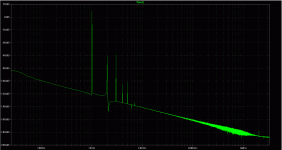
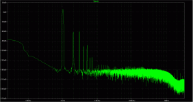
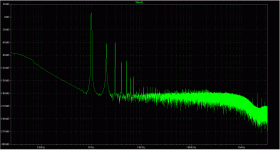
I've got this fft sims (a push pull tube amp at 1W output) same circuit, same conditions , same everything, xcept diff windowing
a default (no windowing)
b Blackman
c Hann
I'm interested to learn which one is most adequate for (analog) audio devices analysis, and , if possible, why
I've got this fft sims (a push pull tube amp at 1W output) same circuit, same conditions , same everything, xcept diff windowing
a default (no windowing)
b Blackman
c Hann
I'm interested to learn which one is most adequate for (analog) audio devices analysis, and , if possible, why
Attachments
the rising to the left "floor" often indicates a settling time tail 0 you need more accurate initial DC solution or to run the sim longer, just fft the last few 10 ms
do you have compression turned off? - add .option plotwinsize=0 to every schematic where you want good analysis resolution - because LT "SwitcherCAD" spice was designed initially with their switcing PS components in mind it uses lossy data compression as default assuming you would neede huge number of switching cycles for good sims
do you have compression turned off? - add .option plotwinsize=0 to every schematic where you want good analysis resolution - because LT "SwitcherCAD" spice was designed initially with their switcing PS components in mind it uses lossy data compression as default assuming you would neede huge number of switching cycles for good sims
Plea for help
Ref:http://www.diyaudio.com/forums/solid-state/249267-help-connection-phase-measurement-3.html Post 29.
I am completely stuck on the TIAN probe implementation.
Ref:http://www.diyaudio.com/forums/solid-state/249267-help-connection-phase-measurement-3.html Post 29.
I am completely stuck on the TIAN probe implementation.
Model files:
I was questioning some of the diode models as they seem too good. They are. So I exported the component file into EXCEL so I could sort them and take a good look at who has what specs. Lots of very "thin" models. I also added quite a few I found. Then I was able to export to a text file and poof! Spice could read the file just fine. Diodes are alphabetical now. Everything SPICE does an update, I'll have to do it again, but it is sure handy to have one simple file.
I was questioning some of the diode models as they seem too good. They are. So I exported the component file into EXCEL so I could sort them and take a good look at who has what specs. Lots of very "thin" models. I also added quite a few I found. Then I was able to export to a text file and poof! Spice could read the file just fine. Diodes are alphabetical now. Everything SPICE does an update, I'll have to do it again, but it is sure handy to have one simple file.
LTSpice actually does a good job at preserving a user's modifications and extensions to the installed component libraries when it updates. Even models you add to the "standard.xxx" database (standard.dio file, etc in the ./cmp/ directory) will be preserved through the update process.. . . Everything SPICE does an update, I'll have to do it again, but it is sure handy to have one simple file.
Dale
Yes, but if you erase the bad models that come default with LTSpice it will put them back. If you REPLACE those models with good models, it will overwrite them with the bad ones. That's why I tried to make this file read-only once. That crashed LTSpice. Hopefully it is just a Linux issue though.
Furthermore, when it does it wipes out all the comments and text formatting so each model fits on one line. Did your models have info and copyright with them? OOPS!!! Gone. The only time this is not inconvenient is when you actually WANT to strip the formatting from a bunch of models - but that's rare.
Furthermore, when it does it wipes out all the comments and text formatting so each model fits on one line. Did your models have info and copyright with them? OOPS!!! Gone. The only time this is not inconvenient is when you actually WANT to strip the formatting from a bunch of models - but that's rare.
LTSpice actually does a good job at preserving a user's modifications and extensions to the installed component libraries when it updates. Even models you add to the "standard.xxx" database (standard.dio file, etc in the ./cmp/ directory) will be preserved through the update process.
Dale
Yes, very happy about that or I would keep all my added ones in a separate file. But it adds new ones on the end and cleans everything up. I find it easier if the list is alphabetical.
It overwrites? Hmmm, that is not good. I have quite a few improved ones from newer vendor specs.
It would be nice if you would share any accurate models you have.
http://www.diyaudio.com/forums/software-tools/158209-spice-transistors.html#post3805991
http://www.diyaudio.com/forums/software-tools/158209-spice-transistors.html#post3805991
I wasn't aware of that behavior. I never tried replacing the supplied models with an improved model having the same name. I always added my own with some unique identifier. E.g., adding a model named "2N3904_CA" (for "Cordell Audio") rather than substituting Bob Cordell's parameters for whatever may be supplied as "standard" in LTSpice.Yes, but if you erase the bad models that come default with LTSpice it will put them back. If you REPLACE those models with good models, it will overwrite them with the bad ones . . . .
I can't offer any suggestions about the formatting, but you can use the standard SPICE comment delimiter ( ";" ) to add any text you want to the end of a .MODEL statement. For example,Furthermore, when it does it wipes out all the comments and text formatting so each model fits on one line . . . .
.MODEL 2N3904_CA NPN(IS=3.5e-15 BF=160 VAF=400 IKF=0.15 ISE=4e-16 NE=1.26 NF=1 RB=30.1 RC=1 RE=0.1 CJE=15e-12 MJE=0.25 VJE=0.75 CJC=3.6e-12 MJC=0.30 VJC=0.75 FC=0.5 TF=380e-12 XTF=30 VTF=4 ITF=0.4 TR=240e-9 BR=0.7 IKR=0 EG=1.1 XTB=1.5 XTI=3 NC=2 ISC=0 Vceo=40 Icrating=200m mfg=Bob_Cordell_Model) ; created February 24, 2011 copyright Cordell Audio
The update process retains the comments. Yeah, you have to open the "standard.*" file to see the information, but at least it's not lost entirely.
I certainly agree with one of your earlier comments: The lack of even a rudimentary capability to catalog and manage device models is a definite shortcoming in LTSpice. Such a capability should be even more essential in a commercial product development environment, where you might create many versions of a device's model to investigate the product's behavior not only with nominal parameters, but also with devices near the extremes of guaranteed values, combinations of HI/LO values among several devices, etc.
(I think the LTSpice developers want us to handle a situation like that by putting all the relevant models in a file, e.g. "Project_Name.mod" and then calling it out on the schematic as " .lib Project_Name.mod ". I don't recall the search hierarchy but I think the files called out in " .lib " statements are searched for particular device models before LTSpice looks at its "standard.xxx" files.)
Dale
- Home
- Design & Build
- Software Tools
- Spice simulation


