@ davorin, are these M102b (or bigger) cores in the transformers? They look very big & powerful 🙂
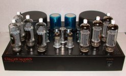
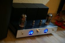
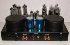
My new amp finally with 6550s
What input tubes are those 6SN7s? It reminds me of the Ella Consonance.
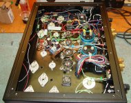
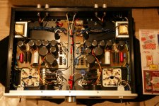
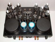
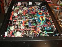
Here's my iteration of Bruce Rozenblit's T8 OTL amp, using custom chassis, toroids, etc. Eight separate power supplies in all. Wiring for one channel shown.
Nice, what output tubes did you use to manage OTL with only 2 pair?
Cool and .....interesting, I sow 2 big caps, with or without capacitor in output?Here's my iteration of Bruce Rozenblit's T8 OTL amp, using custom chassis, toroids, etc. Eight separate power supplies in all. Wiring for one channel shown.
What input tubes are those 6SN7s? It reminds me of the Ella Consonance.
Hi,
the input tubes are russian 6N8S, they are a direct replacement for the 6SN7.
6SN7 is my fav. driver tube. Should sound good then.Hi,
the input tubes are russian 6N8S, they are a direct replacement for the 6SN7.
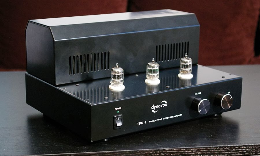
What I want to show in this place is not fully DIY project, but it is advanced tweaking of commercial chinese tube preamplifier.
It looks like this:
Schematics:
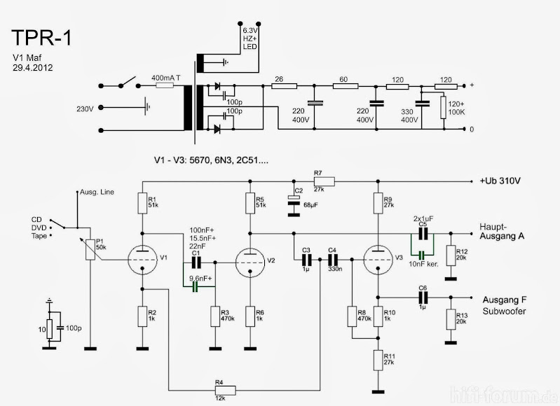
As you can see, the gain is huge, there is NFB loop to reduce gain, and there is a lot of caps (chinese MKT crap) in the signal path. Horrible. So I decided to completely rebuild the circuit. I used SRPP stage galvanic connected to the cathode follower, no NFB at all, and only one good signal capacitor per channel. Only the case and PSU left from original. Now it looks like this:
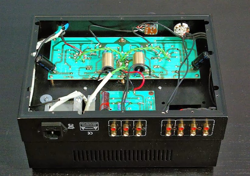
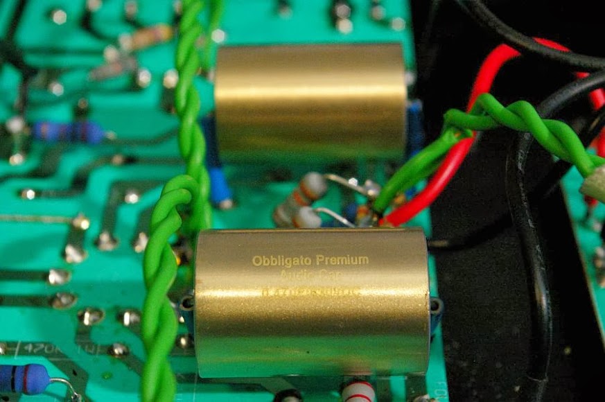
I replaced the potentiometer with metal can Alps and also rotary input switch with Lorlin. The tubes (chinese 6N3) was replaced by NOS 5670 General Electric.
Now the preamp sounds very good, it reminds me Canary Audio CA601 I serviced in the past.
It looks like this:
Schematics:
As you can see, the gain is huge, there is NFB loop to reduce gain, and there is a lot of caps (chinese MKT crap) in the signal path. Horrible. So I decided to completely rebuild the circuit. I used SRPP stage galvanic connected to the cathode follower, no NFB at all, and only one good signal capacitor per channel. Only the case and PSU left from original. Now it looks like this:
I replaced the potentiometer with metal can Alps and also rotary input switch with Lorlin. The tubes (chinese 6N3) was replaced by NOS 5670 General Electric.
Now the preamp sounds very good, it reminds me Canary Audio CA601 I serviced in the past.
Last edited:
Due to extensive asks for the upgraded schematics I post it here:

It's quite simple, isn't it?
It's quite simple, isn't it?
Last edited:
Jono1 - nice tube amp!
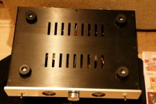
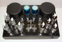
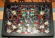
As previously promised - pictures of my first tube inside - not very nice ( i use nos silver plated screened cable for mains and input wires and twisted wires for AC heaters), but its DIY 😎 bottom cover and both channels finally sounds!
As previously promised - pictures of my first tube inside - not very nice ( i use nos silver plated screened cable for mains and input wires and twisted wires for AC heaters), but its DIY 😎 bottom cover and both channels finally sounds!
Attachments
Jono1 - nice tube amp!
As previously promised - pictures of my first tube inside - not very nice ( i use nos silver plated screened cable for mains and input wires and twisted wires for AC heaters), but its DIY 😎 bottom cover and both channels finally sounds!
😱 What do you mean, "not very nice". Man If my little tube amps looked anything like yours I'd be so proud. Your amp looks excellent, not only on the outside, but even the inside. So what if it's not engineered to be perfect, you did what you could, and it looks clean and tidy.
Give yourself more credit, you did a wonderful job!
thank you !
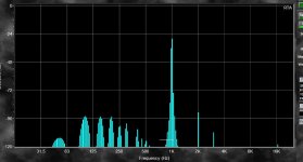
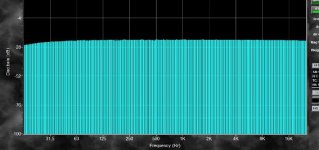
here FR measurement with sound card an hum level. sounds really good !
here FR measurement with sound card an hum level. sounds really good !
Attachments
Last edited:
Jono1 - nice tube amp!
As previously promised - pictures of my first tube inside - not very nice ( i use nos silver plated screened cable for mains and input wires and twisted wires for AC heaters), but its DIY 😎 bottom cover and both channels finally sounds!
I think that it is a great looking tube amp. Simple, clean lines, muted colour tone in the metal (I have seen too many with all too shiny gold lately), tubes are presented so you know what is making the music louder, and all the indicators that you need to make it work properly.
You see it is builds like yours that make me not want to post (but I will one day) and it is builds like yours that give me some insightful ideas to how I would want mine to look.
Thank you very much for the kind words and encouragement.
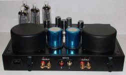
Each channel uses 1/2 of a 12AX7 for gain; two 12FQ7s (12AU7 was originally spec'd), and a quad of EL509 output valves. There is no output coupling cap and the fuses are in the mains supply (not at the outputs).
Each channel uses 1/2 of a 12AX7 for gain; two 12FQ7s (12AU7 was originally spec'd), and a quad of EL509 output valves. There is no output coupling cap and the fuses are in the mains supply (not at the outputs).
I think that it is a great looking tube amp.
What he said. Fantastic job! Very nice work through and through.
Jono

Jono 1
Great to see such a wonderful amp and no Printed circuit boards.
Friend of mine built the same amp but used EL36 X 6 per channel for 50 watts.
Phil
Great to see such a wonderful amp and no Printed circuit boards.
Friend of mine built the same amp but used EL36 X 6 per channel for 50 watts.
Phil
Mcgyver, Very good, diagram, finish, smart election of the topology and valves. Output Low impedance. What any else and anybody must to look for in a preamp?
FINE
FINE
Thanks.Mcgyver, Very good, diagram, finish, smart election of the topology and valves. Output Low impedance. What any else and anybody must to look for in a preamp?
FINE
- Home
- Amplifiers
- Tubes / Valves
- Photo Gallery