Thanks Buzz.
So I will go with 392ohm resistors(closest to 380ohms commonly available) for R7 thru R8 for a approx 26db gain and with 45V rails. Not sure whether these should be 3W or 5W resistors. Can someone please advice.
Also, should the source resistors be 3W or 5W since I am using 45V rails? This for F5TV3.
Thanks.
You could also go with a caddock mp series resistor and just get one 180,or 200 ohm resistor and put a clip on heatsink on it. That way your good to about 15w
Thanks all for your inputs.
It seems that the consensus is that one is playing quite safe sticking with source resistors in parallel of 3W each.
I don't know how to do the power calculations for R7 thru R10 resistors. Am I good with 3W resistors for R7 thru R10 since I am using 380ohms each for an increase in gain to 26db and using 45V rails?
Thanks. Nash
That makes sense for idle conditions, but what about sustained high power operation? Just 64W into 4 ohms is 4A. Divide that into the 2 output devices per rail and you still have 2A per Source resistor (or pair), giving you 2W. A pair of 3W resistors still seems more than you need, but have you considered derating for the elevated temperature inside the case and that the resistor(s) is(are) not mounted in free space?
I know, we aren't likely to actually operate at that kind of power, but shouldn't we be able to operate continuously at rated power? In the big scheme of things, the additional cost of a pair of 3W resistors over a 1W resistor is pretty small. Not to mention that this is DIY where we tend to overdo everything. 😉
when you go beyond the bias current, the diodes starts conducting, resistance gets lower, and current flow thru the diodes, not the resistors.
and even at 2A. you have 0.4*2= 0.8W. a 3W is almost overkill even in this senario. and this is PEAK power. even a 1W resistor will survive this🙂.
PS: i'm not saing dont use 3W resistors. i just say. don't use days thinking, do i need dual 5W or dual 3W🙂
Last edited:
Daniel,
Yes, increasing the gain you can eventually run out of feedback. Decreasing the feedback can alter the character of the amp, but we are only talking about a relatively minor changes. No need to worry about it.
Changing R25 changes the cascode operating voltage. R25 and R27 form a voltage divider. The cascode voltage is Vrail * R27/(R25+R27) With the values in the article the cascode voltage is roughly 1/3 of the rail voltage. Increasing R25 without changing R27 will reduce the cascode voltage and vice versa.
Replacing R27 with a 10-20V zener diode would allow adjusting R25 without affecting the cascode operating point. Pick R25 to allow at least 5 mA through the zener to give it enough current to work with.
if R25 and R27 is of equal value (1/3 of the rail voltage) you can go to a lower value R25 and the same lower value for R27 and you have the same cascode voltage.
EX: if R25,R27 are 10Kohm. you have arond 22V cascode voltage.
if R25,R27 are 4.7Kohm you have the same cascode voltage. and lower dissipation. but this dissipation will not be a problem. ever.
Last edited:
I don't follow your logic on cascode resistors, AudioSan. Lower values of the resistors in the voltage divider will increase dissipation, not lower it. At voltages likely to be found in an F5T dissipation can be an issue if the resistance is below 3K with 20V across it. (For example at 40V rails and 20V cascode voltage) At that point you are at roughly 1/8W so any lower resistance you want to increase the rating to 1/2 W. If we keep resistors above 4.7K I agree that we don't need more than 1/4W resistors.
That aside, my point of mentioning "check dissipation" was more to help establish good procedures - If you are going to alter a design, take a look at more than just the voltage change. Will the current part be suitable for the new operating point? I learned from experience (smoking 10K 1/4W resistors in a pair of A75s hot rodded to 65V rails). Hopefully the newbies reading this will think to check dissipation and not burn anything in other amps they modify.
That aside, my point of mentioning "check dissipation" was more to help establish good procedures - If you are going to alter a design, take a look at more than just the voltage change. Will the current part be suitable for the new operating point? I learned from experience (smoking 10K 1/4W resistors in a pair of A75s hot rodded to 65V rails). Hopefully the newbies reading this will think to check dissipation and not burn anything in other amps they modify.
if R25 and R27 is of equal value (1/3 of the rail voltage) you can go to a lower value R25 and the same lower value for R27 and you have the same cascode voltage.
EX: if R25,R27 are 10Kohm. you have arond 22V cascode voltage.
if R25,R27 are 4.7Kohm you have the same cascode voltage. and lower dissipation. but this dissipation will not be a problem. ever.
Daniel,
Yes, increasing the gain you can eventually run out of feedback. Decreasing the feedback can alter the character of the amp, but we are only talking about a relatively minor changes. No need to worry about it.
Changing R25 changes the cascode operating voltage. R25 and R27 form a voltage divider. The cascode voltage is Vrail * R27/(R25+R27) With the values in the article the cascode voltage is roughly 1/3 of the rail voltage. Increasing R25 without changing R27 will reduce the cascode voltage and vice versa.
Replacing R27 with a 10-20V zener diode would allow adjusting R25 without affecting the cascode operating point. Pick R25 to allow at least 5 mA through the zener to give it enough current to work with.
Hi guys! 🙂
Thank you for your answers!
Actually I know the voltage divider theory. My only doubt was concerned to the fact that being Q7 a bipolar, current from the resistor flows into its base, and I thought that perhaps altering the resistor values, besides obviously changing the voltage ratio, could affect Q7 biasing, because of the new voltage drop value caused by this current. But it must be small enough to be unconsidered. Anyway, I'm going to adopt the Zener, pretty elegant solution I think. What Zener voltage do you think would be optimal?
As for the gain/feedback, good to know. I'm going to calculate the new values.
Spencer says on its build manual to replace R5/6 to 475r to improve bias tuning and R11/12 to 1.21k to improve thermal stability when using Toshiba FETs - my case. What do you think about these changes, Bob?
Thank you
Daniel
Daniel,
The Toshiba devices spec'd for Q7/8 have an hfe of 100-320 so the amount the base current contributed to the divider voltages is largely swamped by the current through the resistors to ground (<1 mA) - good to catch there. Should have mentioned it. The exact cascode voltage isn't critical anyway.
I'm not sure that there is a firm sweet spot for the jfets. It would seem that you wouldn't want to go too low - I've seen 10V described as too low, in the original F5 they run at about 20V and the F5TV2 they are close to 28V. I plan to cascode at 20V whether zener or resistor.
I'd go with Spencer about the changes for your Toshiba outputs unless someone else has anything different to say. IIRC they need less Vgs to turn on.
Bob
Last edited:
Are those changes to R5/6 and R11/12 the result of higher rail voltages from the Turbo setup?
I kept those resistors as spec in my F5 build using Toshiba FETs, didn't seem to have any issues with thermal stability etc.
I kept those resistors as spec in my F5 build using Toshiba FETs, didn't seem to have any issues with thermal stability etc.
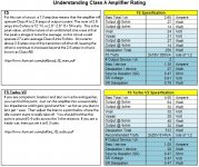
I'm learning and collecting information from PaPa article (F5 and F5T). I realize there have been tons of calculation in this thread, but I try to re-write some kind of summary which I can understand easily and hopefully this can be used as my build guide. Please help to correct if there are things that I got wrong interpretation.
Thanks
Thanks
Attachments

Gadut, I think you have made the fairly common mistake not understanding that the entire bias flows through both n channel and p channel devices. The current in both devices in an F5 biased to 1.3 A is 1.3 A. Dissipation numbers should be double. Similarly in an F5T the current and dissipation is doubled. Remember that the Turbo has two parallel Source resistors, so the voltage stays the same with double the current.
I haven't read your PDF.
I haven't read your PDF.
The bias stays at 1.3A. That comes in through the +ve supply rail passes through the Upper Source resistors and through the upper output device and through the lower output device and through the lower Source resistor and back to the PSU via the -ve supply rail.
The voltage drop is the Rail to Rail voltage (Vrr)
The total dissipation is Vrr * 1.3
Subtract the power dissipated by the sources resistors to find the device dissipation.
The voltage drop is the Rail to Rail voltage (Vrr)
The total dissipation is Vrr * 1.3
Subtract the power dissipated by the sources resistors to find the device dissipation.
Dissipation total still no good, should be around 120 ( or half of your 250) for a stereo F5.
Quiescent dissipation = V rail to Rail * Bias current.
Maximum dissipation = complicated to work out.
Maximum dissipation = complicated to work out.
Max dissipation is minimally 2 x Quiescent dissipation, when PP amp leaves Class A.
Or are you talking about transients?
Or are you talking about transients?
Last edited:
PCB simulation software with JFET and tube component support
Hi all,
is there an affordable PCB simulation software with JFET and vacuum tube component support that anybody know of?
I have considered the free LTspice and am wondering whether I can create my own components in it.
Thanks.
Hi all,
is there an affordable PCB simulation software with JFET and vacuum tube component support that anybody know of?
I have considered the free LTspice and am wondering whether I can create my own components in it.
Thanks.
Bias issue
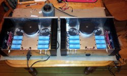
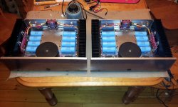
Finally had time to finish my V2 today. I went from CLC to CRC without trying CLC. It is not the good time to mess with experiences with my first amp project, I went with a known path for the PSU. I also cascoded the jfets.
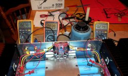
I'm trying to bias tonight. Everything looks good, no smoke, the heatsinks are warm. My issue is that I can't get the bias over 275 mV. I maxed out P1... Is it because I could have low Idss jfets? I don't know their value. Does the remedy is to increase the value of source resistors of jfets? If yes, which value? I have 1 kohm right now. I would like to go at least with a 350 mV bias.
Finally had time to finish my V2 today. I went from CLC to CRC without trying CLC. It is not the good time to mess with experiences with my first amp project, I went with a known path for the PSU. I also cascoded the jfets.
I'm trying to bias tonight. Everything looks good, no smoke, the heatsinks are warm. My issue is that I can't get the bias over 275 mV. I maxed out P1... Is it because I could have low Idss jfets? I don't know their value. Does the remedy is to increase the value of source resistors of jfets? If yes, which value? I have 1 kohm right now. I would like to go at least with a 350 mV bias.
Attachments
My issue is that I can't get the bias over 275 mV. I maxed out P1... Is it because I could have low Idss jfets? I don't know their value.
Doesn't matter, see below.
Does the remedy is to increase the value of source resistors of jfets? If yes, which value? I have 1 kohm right now. I would like to go at least with a 350 mV bias.
Yes, increase the value of the resistor that is in parallel with the pot. (R5 R6) You are pretty close, so 2.2K should be more than enough. Changing those resistors will almost certainly fix your low bias.
- Home
- Amplifiers
- Pass Labs
- F5 Turbo Builders Thread