Not if they are integral to the speakers.
Does anyone make a speaker with a 'cubicle' for introduction of a third party amp? I've not seen one myself so I guess you're talking about a powered or active speaker?
So what?
There are now two cables going to each speaker rather than one. They also perhaps terminate in different places (the component stack is one destination, a nearby mains socket is another).
How does a length of speaker wire make a smaller loop area than the same length of shielded cable? I don't see that at all.
Then as they say 'look closer'. The mains cable to the amp is part of the loop, so is the mains wiring inside the wall(s). See any clearer now? Incidentally its an AC loop only via the transformer(s) interwinding capacitance - appreciable in poweramps with their generally hefty toroids.
"Also interesting to see the notch filter created with the Kimber cable."
I can make something like this happen with 2 meters of cable and a big cap.
All these cable things are explainable by LC at audio.
If all the cables are 1uH and exactly the same capacitance, and the same load is used, I dont expect the differences will be readily apparent - measured or listening.
I use 5mm diameter copper cross section cables BTW. Cables the size of hose pipes just look cool and thats the only excuse I have.
For a bit of nostalgia, did anyone on this thread ever mod or come up with an analog section for the sony xdr tuner? sew some earlier posts then is seem like it went to the wayside.
Everything does not have to be so black and white. So you now accept that all cables are not the same, or whatever you were saying earlier?
.
Oh I'm sure there are some cables that do sound different but if you measured 90% or more of those out there I'm sure they would just pass the signal unaltered.Those other 10% are intentionally flawed.
Good common regular everyday cables made by the "lowly" manufacturers are just that. Cables. They don't try to alter the sound in anyway what so ever.
Boutique pricey cables make all sorts of claims to altering the sound and some of them probably do but that isn't the purpose of a good cable now is it? Does anyone bother to do SBT or DBT on cables? Isn't sighted bias a big factor in "why" cables sound different also?
I find it very amusing that people will pay (insert silly amount of money here) for a simple cable that is supposed to alter the sound. Backwards thinking.So what is it that people want in a cable and do those cables really alter the sound or is it subjective wishful thinking?
Last edited:
It will lead to higher resistance, thats for sure.
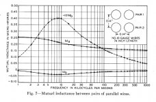
Zm=jwM=-wMa+jwMb , Ma and Mb also being funktions of f.
To elaborate a little more on the mutual resistance due to the proximity effect.
From the figure below: Zb = -0.04 uH / ft (at 10 khz)
Re [Zm] = 37.7 mohm/5m (2.5 m cable at 10 khz)
Rdc = 16.4 ohm/5m (10 awg)
Re [Zs] = Rdc (assuming at 10 khz)
Rtot ac = 70 Mohm (at 10 khz)
This corresponds to 16 awg at 10 khz.
I think my numbers are correct and that it means 20 db at 10 khz at 6.8 ohm load.
Attachments
Oh I'm sure there are some cables that do sound different but if you measured 90% or more of those out there I'm sure they would just pass the signal unaltered.Those other 10% are intentionally flawed.
Good common regular everyday cables made by the "lowly" manufacturers are just that. Cables. They don't try to alter the sound in anyway what so ever.
I Can see that you are referring to boutique cables which sound diferent because they "alter" the sound. What you may not know is that even ordinary cables sound different, so the question is which one "alters" the sound?
What mostly makes the cables sound different is the material they are made of. Fifteen years ago all cheap cables were made of copper, now most are made of aluminum. Copper and silver sound completely different. Then between coppers, there's purity.
Several posts ago Frank posted about how two cables which sound different became "similar" after they were soldered to both ends. Why is that? That's because the material of the "plug" is "critical" (often the weakest link).
If I'm not mistaken, boutique cables (power cord for example) use rhodium for the plug.
I think some cables have different resistance, but I don't think it is this resistance differences that matters (or could be if it resonates with L and C) because the sound can be fatiguing with some cable (resistance alone should not be responsible with fatiguing sound). Aluminum tends to be fatiguing and may be flat foil tends to be fatiguing as well. Surprisingly, I have 2.4mH flat coils from Intertechnic which looks like aluminum, but sound good in one of my speaker.
Last edited:
To elaborate a little more ....
Typo... 70 mohm is 40 db!
(I'm not allowed to edit my posts yet, sorry.)
More specifically, time difference caused by variation of the load impedance.Pavel
I think that jn makes a case not for a specific frequency but for the time difference that occur btn the LF and HF content of audio spectrum:
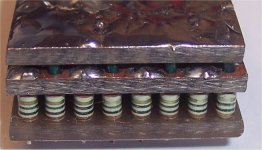
No. That resistor had a lower limit on inductance based on the tube to tube distance, an air dielectric coax structure. The resistors and the return currents between them did work the inductance down significantly, but there was an asymptote in inductance no matter how many resistors I paralleled.jn
Is the low inductance sense resistor you fabricate for Scott like one of these two you described here?
I've since adopted a matrix style structure which is very scaleable, and allows me to also make voltage dividers with two different value composite resistors interleaved. I'll look for a pic.
The 200 element LC should be very close to the t-line. It's just two different models of the same thing. As the number of LC's increase, it certainly converges. The only things I do not like about a 200 element LC model, is it requires some comp horsepower, and it doesn't give a good feel for what's going on.I entered Mr. Bateman's 200 unit simulation and compared the step response with the lumped equivalent of all 200 at the source. I used 10k as the frequency his 14 Ohm line and 1 Ohm load. Note, in general you can not do a simple transient response with frequency dependent components. Still this is sort of what I expected, kind of a conservation of energy thing.
In a funny way I think we are all agreeing, I'm just saying the Tline as a bulk component gives the same time constant/phase behavior.
Two notes on your model. You included an inductive discontinuity, hence the ringing.
And as I've been stating since day 1, you show the settling time I've been talking about all along. If you sim it as my graph shows, you'll see the cusp I speak of.
I'll try to check my cvr if I can to see how much parasitic L it has.
The difference in speed is not fictional. At audio frequencies cables are dispersive. However, this is irrelevant unless you are wiring a trunk telephone system.
And make the assumption that humans cannot discern ITD in teh 5 to 10 uSec range.
But you are assuming telephone level fidelity.That's it. We are not at the telephone forum here and we are not working with kilometres of cables in high end audio.
LOL..That was funny.Wow, that is weapons-grade stupid.
Condemnation without examination is prejudice.It has an impact on speed of propagation along the wire - which is totally unimportant for audio waves and length of speaker cables.
jn
But you are assuming telephone level fidelity.
Empty phrase without proof and without any basis.
One odd note: Why is the 200 unit sim lowering it's ring frequency with time, and why is it becoming less damped with time?I entered Mr. Bateman's 200 unit simulation and compared the step response with the lumped equivalent of all 200 at the source.
jn
My telephone is monophonic.Empty phrase without proof and without any basis.
The fidelity of my telephone does not require control of interchannel frequency dependent delays.
My stereo is a two channel entity. The virtual image caused during stereo reproduction requires more control than a mere telephone.
You may wish to apply telephone level accuracy to stereo reproduction, but that's just you.
Do you consistently attack without thinking?
jn
Reverberation time for an impulse, settling time for a voltage step, and frequency/phase response for a low frequency (e.g. audio) excitation are all different ways of looking at the same thing. If there is a real problem, as jn suspects, then it would have first appeared in long microphone cables in concert halls - not short interconnects or speaker cables in home audio. It didn't, so it isn't.
Finally, you are starting to get it.Reverberation time for an impulse, settling time for a voltage step, and frequency/phase response for a low frequency (e.g. audio) excitation are all different ways of looking at the same thing
I've been telling you that for over a year now.
When did interconnects enter into this discussion??? Don't try to divert.If there is a real problem, as jn suspects, then it would have first appeared in long microphone cables in concert halls - not short interconnects or speaker cables in home audio. It didn't, so it isn't.
Now, please go read something about microphone cables, how they work, what impedance they are, how they are terminated. Engineering understanding of the issue would help you here.
To wit:
Mikes are not milliohm level impedance sources, and they are NOT terminated with an impedance which varies one or two orders of magnitude across the audio band.
There are significant differences between what you mis-apply to the discussion, and reality.
jn
What mostly makes the cables sound different is the material they are made of. Fifteen years ago all cheap cables were made of copper, now most are made of aluminum. Copper and silver sound completely different. Then between coppers, there's purity.

Let me guess, silver sounds brighter...
Here's an earlier one I used. Note that the drive conductors are not a twisted pair, just the kelvins.. This was being used for measuring the response of a coil from 100 milli-hz out to 1Khz, the parasitic inductance was of no concern, just how well the resistor prevented dI/dt caused inductive voltage errors.Is the low inductance sense resistor you fabricate for Scott like one of these two you described here?
George
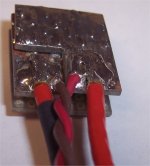
I ran the vtap wires from the drive edge, but for better hf accuracy they should be connected at the physical center of the resistor. The one I'm making will be done that way. I'll also be using #14 for the drive wires, and kynar wire wrap for the taps, twisted of course. Scott, hope that doesn't make it difficult.
BTW, that slantfin model worked great for some testing I had to do, 10 ampere 50 uSec wide pulses with 10 uSec rise/falls...all through a 6 cable cat5e set configured for 4 ohms. No ringing..
jn
Attachments
Last edited:
I got that in 1973 in first-year electromagnetism when we learnt about the low frequency approximation, otherwise known as circuit theory. My concern has always been that you haven't got that.jneutron said:Finally, you are starting to get it.
Like all audio cables, they don't have 'an impedance'. They vary across the audio frequency range.Now, please go read something about microphone cables, how they work, what impedance they are, how they are terminated.
Granted, but they are much longer than a typical speaker cable.Mikes are not milliohm level impedance sources, and they are NOT terminated with an impedance which varies one or two orders of magnitude across the audio band.
'Delays' will be similar on the two channels. Any difference will primarily result from speaker pair mismatching, which will have frequency response implications anyway.The fidelity of my telephone does not require control of interchannel frequency dependent delays.
You keep asserting that there is an issue here. I have yet to see any evidence. You have at last admitted that what the cable does is equivalent to circuit theory, so is just a matter of filtering. Obviously, if the cable L and C reacts with the load to produce a bumpy response then this will be audible but we all knew that anyway.
Despite my making these statements for over a year to you.I got that in 1973 in first-year electromagnetism when we learnt about the low frequency approximation, otherwise known as circuit theory. My concern has always been that you haven't got that.
Yup.. and they are terminated to 600 ohms. Not 1, not 1 through 100, but 600 ohms.Like all audio cables, they don't have 'an impedance'. They vary across the audio frequency range.
So? Look at scott's depiction of settling time. 1 ohm load, 14 ohm line.Granted, but they are much longer than a typical speaker cable.
The settling time is load dependent. Mikes do not suffer two order of magnitude mismatches.
Despite the load having severe frequency dependent impedance therefore frequency dependent delays?'Delays' will be similar on the two channels. Any difference will primarily result from speaker pair mismatching, which will have frequency response implications anyway.
Despite humans having ITD sensitivities in the low microsecond regime?
You're zest to paint with an overly broad brush does you no service.
I stated that on this thread about a year ago. I love your re-writing history to meet your desires.You keep asserting that there is an issue here. I have yet to see any evidence. You have at last admitted that what the cable does is equivalent to circuit theory, so is just a matter of filtering.
Again, diversions.. It's interesting watching you jump from one thing to another.Obviously, if the cable L and C reacts with the load to produce a bumpy response then this will be audible but we all knew that anyway.
jn
No, not 'despite' but 'because'. Obviously an LC circuit will have a frequency-dependent response if it is loaded with a frequency-dependent impedance.Despite the load having severe frequency dependent impedance therefore frequency dependent delays?
I now genuinely do not know what you believe you are claiming. You seem to be agreeing with me, yet at the same time strongly disagreeing. You accept that the low frequency approximation is valid, yet you say that RF effects somehow show a different cable behaviour which means that the LF approximation is not valid. You say that these effects are audible due to inter-channel delays, yet in a matched system the delays would be the same in each channel and therefore inaudible (part from any frequency response issues which would show up in the lumped version anyway).
Could you please restate your position, showing where you differ from me (and others). You keep making claims about these time delays but we can't pin you down.
- Status
- Not open for further replies.
- Home
- Member Areas
- The Lounge
- John Curl's Blowtorch preamplifier part II