Monitoring what nodes? The test points? The PSU rail+?Would a fixed V-meter disturb sound? Surely there are cheap V-meter modules with several Mohms input resistance and of course they have some capacitance as well.
One could have a 5pos rotary 2pole switch to show the different voltages...
Regards
What are the extremes of tp1/tp2? Lowest/highest?
Regards
+/-1V around 3.6V TP1 to TP2. If your Q1,Q2 heat up wilder than that then raise your R2, R3 by 1 Ohm value. Ambient temperature equilibrium in a boxed build helps a lot if you will reset for when warmed up. The 369s are prone to draw more IDSS as their temperature rises. That gets under more control as the sensitivity versions get lower so the Rs R2,R3 go higher. In LMC we make economy in value to save on additional Johnson noise contributed by R2//R3. Just Blow over Q1,Q2 and you will see how sensitive in temp they are in LMC. Use the mini sinks. Its a matter of centering the voltage bias, THD does not change.
Yes...🙂
I would avoid parasitic inductance and capacitance there, especially across TP1-TP2. Very sensitive signal node.
+/-1V around 3.6V TP1 to TP2. If your Q1,Q2 heat up wilder than that then raise your R2, R3 by 1 Ohm value. Ambient temperature equilibrium in a boxed build helps a lot if you will reset for when warmed up. The 369s are prone to draw more IDSS as their temperature rises. That gets under more control as the sensitivity versions get lower so the Rs R2,R3 go higher. In LMC we make economy in value to save on additional Johnson noise contributed by R2//R3. Just Blow over Q1,Q2 and you will see how sensitive in temp they are in LMC. Use the mini sinks. Its a matter of centering the voltage bias, THD does not change.
Q1/Q2 has ambient temp... So in the extremes tp1/tp2 2.6v-4.6v?
Regards
I would avoid parasitic inductance and capacitance there, especially across TP1-TP2. Very sensitive signal node.
Ok, no VMs then🙂. Actually I just want to get ready with it, hide it and enjoy😀
Regards
Q1/Q2 has ambient temp... So in the extremes tp1/tp2 2.6v-4.6v?
Regards
You always compensate when setting for warm up time and environmental temp for it to hover close to 3.6V TP1-TP2 in the end. Takes ~10 minutes to settle from power on. If it tends to travel more than +/-1V until warm you probably got wilder IDSS and you try raise your R2, R3 by 1 Ohm first.
*As I have wrote one time before I avoid to actively CCS Q1, Q2 for LMC mode bcs that would inject its current noise directly in the 369s. Better compensate carefully for an acceptable settling and keep it natural there. High transconductance JFETs are positive Tempco strongly, I don't want to force them.
Actually I just want to get ready with it, hide it and enjoy😀
Regards
I only got 3 Ohm Rs//Rs (R2,R3) in my proto bcs those I had in hand in better quality at time of build vs proper 3.9 for my 11mA JFETs and has more cold to warm travel than most builds. After I boxed it and set it up for warm box ambient I did not revisit it. Never sounded like changing drastically even when I power it on and I start spinning records from cold. After half an hour it sounds generally bit better as most audio electronics do, that's all I have seen. Most of it getting better I suspect its the class A power amp I use though.
I only got 3 Ohm Rs//Rs (R2,R3) in my proto bcs those I had in hand in better quality at time of build vs proper 3.9 for my 11mA JFETs and has more cold to warm travel than most builds. After I boxed it and set it up for warm box ambient I did not revisit it. Never sounded like changing drastically even when I power it on and I start spinning records from cold. After half an hour it sounds generally bit better as most audio electronics do, that's all I have seen. Most of it getting better I suspect its the class A power amp I use though.
I use 5R6 R2/R3 for my 12.4mA JFETs - are these good or should I replace them with 5R1?
Regards
These are good. Better balance between degeneration and IDSS than in mine for instance. See your drifts after you got a box, now its rather useless to bother much. Do you use the minisinks? Those help.
Susumu RG and Vishay TNPW are smd resistors and available from Mouser. Miniohm resistors are a smaller wattage version of Econistor and Squaristor resistors and are available from Rhopoint Components. Some values are stocked in Farnell as well.
Precision (through hole) - Resistors - Components
Edit: You can buy directly from rhopoint components but you have to register an account first and then ask for a quote
Thanks very much, skouliki.
Andy
As my p/s is 1mtr from the FSB would there be any advantage in having extra capacitance next to the phono pcb's?
You could use 100uF/63V instead of 0.1uF C3x for simplicity. Listen before and after. Maybe under the board to keep leads short. Or on top just leaning over R6x.
These are good. Better balance between degeneration and IDSS than in mine for instance. See your drifts after you got a box, now its rather useless to bother much. Do you use the minisinks? Those help.
Yes I use the minisinks. Yepp, it's seemingly a moving target unboxed.
I'll wait. Thanks.
Regards
There is VR1 too to utilize also, if you haven't.
I have 🙂. But as said - wait until boxed...
Regards
Last edited:
You could move your input coax directly on the pins of your 5K load resistor to skip layout distance also. You don't have the DIP and other load options in use for now, so why not.
Next thing to do 🙂
The capacitors I have been waiting for were shipped by Mouser Wednesday night... Sorry for the OT rant, I was really hoping to finish these circuit boards this weekend!
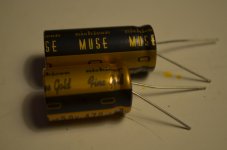
Needless to say, I received no call on the weekend. Finally got the caps tonight. If anyone is wondering about the physical difference between Nichicon FG "Fine Gold" and KZ "Muse", here they are:

They are both 470uF/50V.
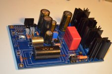
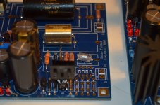
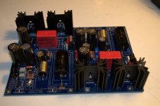
With those in place I have finally finished the main circuit boards:


I feel like now I can focus on the PSU.
- Home
- Source & Line
- Analogue Source
- Simplistic NJFET RIAA