... the Barney Oliver condition implies: RE = 1/Gm, while I stated: RE = 0.5/Gm. So that's another condition (the Edmond Stuart condition
Sorry, I missed the factor of 2 difference from Oliver.
Just the lowest distortion... pre-simulator era
Yes I assumed lowest distortion.
But I wondered what the (pre-simulator) derivation was.
Somewhere in the order of 1/Gm seems reasonable.
Not clear where the specific value comes from.
Best wishes
David
Sometimes I use 2N3904/3906 in quad arrays for current mirrors,
Sonny the stacked Wilson you have here are they better than a single with a beta helper..??
Also I have seen problems by cascoding with jfets, with low current it's no problem at all, but if you want to push some current it can be hard to find high IDSS pairs. The jfet cascode gives significant impedance improvement especially in the higher frequencies.
2N3904 and 2N3906 is a good sounding transistor. My first CFA amp had this transistor and did outperform accuphase by several shoe length!!!! 16 years ago. 😀
Hi David,[..]
But I wondered what the (pre-simulator) derivation was.
Somewhere in the order of 1/Gm seems reasonable.
Not clear where the specific value comes from.
Best wishes
David
It's some 30 years ago I figured it out. It was a kind of "spin-off" from fiddling with the Black-Scholes option model (in an attempt to make money, ha-ha), which contains some exponential expression. How I did it exactly, I can't remember anymore, but I do remember that in the end I've checked the condition for minimal distortion by plotting the incremental Gm* (of the entire input circuit) at various values of RE. Yes, I did use a computer, a DEC PDP11, for plotting the results. So in this aspect, after all, it was a simulation.
Cheers, E.
* thus voltage in and not current in.

It's some 30 years...
Thanks Edmond.
The value looks plausible even if you can't remember the details.😉
Best wishes for the New Year.
David
Edmond, you are dating yourself, a 12 bit octal PDP-11 wow, did you use paper tape to load it?
Our team used it to test modules of the F-15 Fire control and radar systems for the Saudis.
Our team used it to test modules of the F-15 Fire control and radar systems for the Saudis.
Last edited:
... a 12 bit octal PDP-11 wow, did you use paper tape to load it?
Paper tape? We used to dream of paper tape.😉
WE had to set a switch manually for every bit to enter each line of code.
Seriously, that's how it was boot loaded.
Best wishes
David
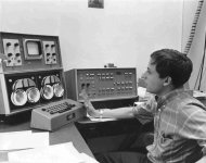
This is the first computer that DEC made. They built it for Lincoln Labs at MIT, I worked on it at Washington University Med School in St. Louis.
The big cable going to the right in this photo were to the COMPUTER, the input console sat on the desk...
The PDP 11 had more than 12 bits, but it was still Octal.
The big cable going to the right in this photo were to the COMPUTER, the input console sat on the desk...
The PDP 11 had more than 12 bits, but it was still Octal.
Attachments
Thank you on feedback resistor comment.
I would apreciate if you comment the compensation I used hare, http://www.diyaudio.com/forums/solid-state/243481-200w-mosfet-cfa-amp-43.html#post3753533
It is a kind of OIC (output included compensation) and I could achieve with it quite high slew rate and exellent phase and gain margin.
BR Damir
Hi Damir,
I hadn't seen this post before. Some impressive results with the CFA and 4 sets of output MOSFET pairs.
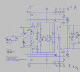
It looks like the two 15pF capacitors are the primary Miller compensation, which is applied joitly through the 150pF capacitors to the upper and lower VAS inputs. However, I'm not sure I understand the role of the 100pF capacitor that leads from the amp output back to the joined 150pF capacitors on the VAS input side. Is it some kind of a lead capacitance from the output to the interior of the amp that bypasses the input stage at HF for improved stability? Hope I'm reading the schematic right.
Cheers,
Bob
/OT
Hi Kris,
The PDP11 was a 16 bits machine. In the early seventies however, we did have a 12 bits machine, the PDP8
As David remarked, you must toggle 12 switches (one for each bit) several times, i.e. word for word. I can't remember how many words (maybe 10?). In this way the so called bootstrap loader was entered, which in turn started the paper tape reader to load the operating system, called OS/8 (hope I'm correct).
THOSE WERE THE DAYS 😉
Cheers, E.
Edmond, you are dating yourself, a 12 bit octal PDP-11 wow, did you use paper tape to load it?
Our team used it to test modules of the F-15 Fire control and radar systems for the Saudis.
Hi Kris,
The PDP11 was a 16 bits machine. In the early seventies however, we did have a 12 bits machine, the PDP8
As David remarked, you must toggle 12 switches (one for each bit) several times, i.e. word for word. I can't remember how many words (maybe 10?). In this way the so called bootstrap loader was entered, which in turn started the paper tape reader to load the operating system, called OS/8 (hope I'm correct).
THOSE WERE THE DAYS 😉
Cheers, E.
Last edited:
Yes, those WERE the days. I remember toggling in the boot-strap loader every time you wanted to run the machine/software. We had a lot of PDP-11/RT-11 in use and I was able to put together a whole system from spare boards and used it at home. I used it with DADisP software --- which is great as you can do circuit changes and see results in real time plotted on the screen. Watching a MontiCarlo run and see the curve change on the screen is Still very cool.... SPICE was young and clumsy then.... even with the math co-processor IC. But it was fast as the archectchure was developed for number crunching. Once, I used the PDP-11 for an interface to run/gather data for an experiment called Coal Gasification.... now used to extract gas from deep underground coal seams. Lots of fun stuff. Then HP bought DEC and soon afterwards the PC was taking over and DEC is no more. BTW - the early Microsoft op system was taken directly from the DEC system.. stripped down.
Thx-RNMarsh
Everything you learn today will be obsolete, tomorrow.
Thx-RNMarsh
Everything you learn today will be obsolete, tomorrow.
Last edited:
Hi Damir,
I hadn't seen this post before. Some impressive results with the CFA and 4 sets of output MOSFET pairs.
It looks like the two 15pF capacitors are the primary Miller compensation, which is applied joitly through the 150pF capacitors to the upper and lower VAS inputs. However, I'm not sure I understand the role of the 100pF capacitor that leads from the amp output back to the joined 150pF capacitors on the VAS input side. Is it some kind of a lead capacitance from the output to the interior of the amp that bypasses the input stage at HF for improved stability? Hope I'm reading the schematic right.
Cheers,
Bob
Hi Bob,
Yes you are reading correctly what I tried to accomplish with this compensation. Only what is different here is that the Miller is a secondary compensation(sometime in this position a shunt compensation is used) to get better PM and GM and the primary compensation is C8 (100p) used as OIC or as some call it pure Cherry from the output via two 150p caps(C6, C9) to the VAS input. In this way OPS is inside the compensation and THD20k is about 10 dB lower then if I use MIC.
Thank you for your time and the best wishes
Damir
The 😎🙂 award.
Yes, those WERE the days. I remember toggling in the boot-strap loader every time you wanted to run the machine/software. We had a lot of PDP-11/RT-11 in use and I was able to put together a whole system from spare boards and used it at home. I used it with DADisP software --- which is great as you can do circuit changes and see results in real time plotted on the screen. Watching a MontiCarlo run and see the curve change on the screen is Still very cool.... SPICE was young and clumsy then.... even with the math co-processor IC. But it was fast as the archectchure was developed for number crunching. Once, I used the PDP-11 for an interface to run/gather data for an experiment called Coal Gasification.... now used to extract gas from deep underground coal seams. Lots of fun stuff. Then HP bought DEC and soon afterwards the PC was taking over and DEC is no more. BTW - the early Microsoft op system was taken directly from the DEC system.. stripped down.
Thx-RNMarsh
Everything you learn today will be obsolete, tomorrow.
Yeah that was the OPSystem that MS bought from Seattle Computing for 50K and sold to IBM for a million, Gates was riperoffer from the get go.
This is What I get with Cherry compensation, Hawksford cascode on the input pair (no diamond) current mirror with gain to the VAS with Hawksford cascode.
+/-33V 20Khz into 4 ohms
Fourier components of V(out)
DC component:-3.12431e-006
Harmonic Frequency Fourier Normalized Phase Normalized
Number [Hz] Component Component [degree] Phase [deg]
1 2.000e+04 3.253e+01 1.000e+00 -2.79° 0.00°
2 4.000e+04 8.312e-05 2.555e-06 -3.05° -0.25°
3 6.000e+04 1.397e-04 4.296e-06 90.60° 93.40°
4 8.000e+04 1.953e-05 6.002e-07 33.16° 35.96°
5 1.000e+05 5.868e-05 1.804e-06 99.01° 101.81°
6 1.200e+05 1.212e-05 3.725e-07 32.71° 35.51°
7 1.400e+05 4.923e-05 1.514e-06 109.77° 112.57°
8 1.600e+05 4.016e-06 1.235e-07 36.50° 39.30°
9 1.800e+05 2.909e-05 8.943e-07 125.14° 127.93°
Total Harmonic Distortion: 0.000564%
Now numbers aren't that important, what is important how the amplifier reacts to reactive loads, how GND is modulated and and the list goes on and on. The numbers are however quite encouraging and shows that the circuit has tremendous potential.
I like to close the loops as close as possible to the problems, And I believe that this is exactly the benefit of cherry compensation. In CFA's it seems possible while still maintaining unconditional stability.
Attachments
If this is right, i feel that i have been accepting D.self comment, without question it, about incorporate the output stage into circle of miller compensation.
He stated it could be very unstable. Now i have to test it. Thanks for enlighten me Dadod, MiiB and Esperado
- Sonny
He stated it could be very unstable. Now i have to test it. Thanks for enlighten me Dadod, MiiB and Esperado
- Sonny
Last edited:
If this is right, i feel that i have been accepting D.self comment, without question it, about incorporate the output stage into circle of miller compensation.
He stated it could be very unstable. Now i have to test it. Thanks for enlighten me Dadod, MiiB and Esperado
- Sonny
Free yourself from convention. 😉
Output inclusive compensation looks stable in sims. Give me a week or so and will have tried it in reality... onto prototype number 5. The previous 4 are all blown due to experimentation. 😀 Its the only way to learn.
I also have an amp I can test it on.
3 spareboards assembled 😉 already.
But it will not be before 2 weeks time.
3 spareboards assembled 😉 already.
But it will not be before 2 weeks time.
If this is right, i feel that i have been accepting D.self comment, without question it, about incorporate the output stage into circle of miller compensation.
He stated it could be very unstable. Now i have to test it. Thanks for enlighten me Dadod, MiiB and Esperado
- Sonny
Amazingly, D. Self was unaware of Cherry's papers about output inclusive compensation. Moreover, also the way he was building and testing amps with way too long leads to the output transistors (I've once seen a picture, about 8", aaargh!) made it impossible to get such a compensation scheme stable.
Cheers, E.
In sims have noticed output inclusive compensation seems to give most improvement in THD at higher power levels. Is this a general behaviour for OIC or just case specific?
Sonnya - I work on strip board these days. If I can get it stable (and sounding good) on strip board then I'll consider getting PCBs made.
Sonnya - I work on strip board these days. If I can get it stable (and sounding good) on strip board then I'll consider getting PCBs made.
- Home
- Amplifiers
- Solid State
- CFA Topology Audio Amplifiers