Member
Joined 2009
Paid Member
My response on the other thread may not have been clear, my vote is that you must return the feedback shunt current to the input lifted ground.
Richard, correct engineering require your amp is able to output square waves at full level indefinitely. No way to undersize power feedback resistance under this point.I would not make that conclusion without testing its assumption at a reasonable - sustained - high average output from a 100-200W PA.
What i wanted to lighten is the margin you'll like to add for reasonable temp/distortion in this resistance. Musical Peaks are 12db more than average. (peak meters/vu-meters) and vu-meters are not 0dB all the time. Plus the X1.4 between square and sinus, it makes at least >X5 margin in normal use. Can be enough ? I believe yes, and add that, most of the time, we run our amps way under their max power.
And, if it is PA at full power, who care about hifi ?
Just a though.
In a ideal world, we'll like to size each resistance in the feedback bridge for they reach the same temp for the feedback ratio remain the same, whatever their temp behavior...
Last edited:
A PA at full power should be hifi ... I heard it done, several times, obviously by people with a few more marbles rattling around up top - so there are no excuses for the normal rubbish ...And, if it is PA at full power, who care about hifi ?
Just a though.
Man we are talking of real high end...resistance's distortions in a concert hall, go figure !A PA at full power should be hifi
Real high end is what comes out of the speakers - not the simulated, or measured on a workbench, isolated component performance. 120dB performance somewhere in the chain means nothing if the next bit struggles to achieve 60dB ...
My response on the other thread may not have been clear, my vote is that you must return the feedback shunt current to the input lifted ground.
After reading about thermal distortion , having the FB "out on a wire" might
be best. I also could return it anywhere I like.
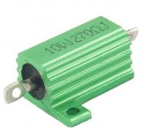
A couple of large resistors(below) "outboard" (with the cap). Lo-Z in CF
would allow this - unlike a VFA.
PS - we don't have to be cheap , like Pioneer.
OS
Attachments
Last edited:
Wirewound and long wires at MHz ? hum...A couple of large resistors(below)
Last edited:
Wirewound ? hum...
Or ... (like bob suggested - below)
Non- inductive 50 watter !
OS
Attachments
Wirewound and long wires at MHz ? hum...
Lo-Z , shield them if you like.
As a gross example - the original leach has it's OP's out on" long wires"
It's at Mhz , as well. Still works.
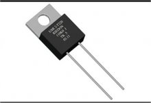
With those to-220 resistors, all can stay firmly planted on the pcb.
OS
I just put 5 0.5W resistors in parallel on my amps. Works well. (Good quality 25 ppm devices with low voltage coefficients)
Last edited:
Member
Joined 2009
Paid Member
But, is there any thing really wrong with a single 3 w unit (thick film) ?
mouser has them for $.50 -.80 .... http://www.irctt.com/file.aspx?product_id=36&file_type=datasheet
I have option for a 3W or the to-220 already done.
OS
mouser has them for $.50 -.80 .... http://www.irctt.com/file.aspx?product_id=36&file_type=datasheet
I have option for a 3W or the to-220 already done.
OS
Or ... (like bob suggested - below)
Non- inductive 50 watter !
OS
😎🙂
But, is there any thing really wrong with a single 3 w unit (thick film) ?
mouser has them for $.50 -.80 .... http://www.irctt.com/file.aspx?product_id=36&file_type=datasheet
I have option for a 3W or the to-220 already done.
OS
😎🙂
Plus the X1.4 between square and sinus, it makes at least >X5 margin in normal use. Can be enough ? I believe yes, In a ideal world, we'll like to size each resistance in the feedback bridge for they reach the same temp for the feedback ratio remain the same, whatever their temp behavior...
😎🙂
Its all good.
I'll try the visualization method of communication.
Below is the ground scheme , I use this for VFA , but I tie the "drawn"
R-C to the lifted ground. Both NFB and G2 will be wires bridging the PCB.
OS
Do it the way Bonsai does it... I do it same way, if I understand his description correctly.
Thx-RNMarsh


Yes, I have done that and agree it is a good sounding solution.....voltage coefficients, noise cancellation and/or something, but it does do good things subjectively.I just put 5 0.5W resistors in parallel on my amps. Works well. (Good quality 25 ppm devices with low voltage coefficients)
Multiple parallel output stage emitter resistors also.
Dan.
...let's see how we can improve a CFA input stage. We know already that for lowest distortion RE = 0.5/gm = 0.5 VT / Ic or 13mV / I ...
Hi Edmond.
Nice to see a perceptive post on this topic, there has been little discussion of optimisation.
But the Oliver condition that 2*RE = 1/Gm was derived for minimum crossover distortion in class B+ circuits.
It is not obvious to me that it is still optimal in this case, what's your rationale?
Compliments of the season and
Best wishes
David
- Home
- Amplifiers
- Solid State
- CFA Topology Audio Amplifiers