I just used a ceramic trimmer that I repurposed from an old oscilloscope. It's pretty noncritical, the adjustment is just for feedback compensation to prevent any ringing or overshoot on square waves.
My boss has a Quad 44 with the tilt control. His also has a bass lift / cut, that would be a separate adjustment?
Yes- I haven't copied that part of it. 😀 I think it's just a simple RC shelf circuit like the old "loudness" switches.
Jameshillj, below is how I modified design. The top response curve is with the tone controls flat, as per audio taper potentiometers with their center point being 10% the total value. I represent this with a 450k and 50k pair of resistors. The bottom curve is with the bass turned up a bit. There is a 1.25dB dip for more than 5dB of boost enhancement. While this is only theory, the design is now better than some commercial preamp's tone controls. Here is what I did to the interstage circuitry:
An externally hosted image should be here but it was not working when we last tested it.
Looks great!
Found this thread a few days ago finally have some time to respond. Attached is a pdf of a bass-mid-treble preamp I did with 6SN7's. As it stands now it has a gain of about 6 which is really too much. I still need to make R5 larger still to throw away even more gain.
The schematic as posted has the pots simulated with fixed resistors. I need to modify it to use "real" pots so as to show the plots.
I have the LTSpice file available for anyone who wants it.
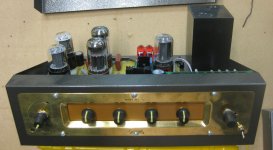
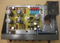
The pic shows how it was installed in an old Eico chassis. The board is a tubesforhifi SP9 octal tone line control board that has completely different components and topology than originally designed for 6SL7's.
The schematic as posted has the pots simulated with fixed resistors. I need to modify it to use "real" pots so as to show the plots.
I have the LTSpice file available for anyone who wants it.
The pic shows how it was installed in an old Eico chassis. The board is a tubesforhifi SP9 octal tone line control board that has completely different components and topology than originally designed for 6SL7's.
Attachments
Ah, I see a buffer on the input and a buffer on the output - nicely done
Could you fit the volume control pot between U2 and U2?
With approx 300V on the anodes of U1 and U4, are these buffers using one valve with a raised heater voltage, maybe about +100V for the common heaters?
With the Aikido gain stage, the 6SN7s 'seemed to prefer' a current between 5 - 10mA - does this also apply here?
Can the network of C11, C13, R20, R21 be simplified?
Could the 'tone-pots' (R10, R11 and R13, R14) be substituted by stepped 'L-pads'? (maybe with those 11 position 2 pole switches?)
I'm full of questions!
OK Great so what are you using for your reference when you tune your system? What equipment?
Can you give me a practical tone setting for single 8' foot couch in a 12' x 20' room? I would like to try it. If it works I will say so and continue to bring in furniture so long as you can still recommend equalizer settings for me.
There is only one catch, the couch is made of solid wood.
As silly as this sounds my experience has been, as many others, that the better your system is, the less you need compensate. Honestly it feels liberating.
By better, I mean well matched, not necessarily expensive or trendy.
Most amplifiers will sound better with the absence of tone controls, for a variety of reasons, even if they are zeroed out.
You may find by speaker rolling you get the results you are after.
Example: I recently took a chance on some older brown box Polk 10A speakers, for $250 and some new caps it's a match made in heaven for a little SE amp. I might dare say it has a touch too much bass at low volume levels compared to an ideal linear response.
As usual a very mature response as usual.
Pleas contribute something positive or useful to the conversation.
Pleas contribute something positive or useful to the conversation.
A few comments on that schematic posted by Kouiky (no criticism intended, perhaps just an erroneous sketch).
Firstly I would leave out R24. It will influence the rotational 'law' of the tone pots, loading them too much. You have a d.c. grid path to common via R8-R11-R12. If you feel better with a grid return resistor, increase R24 to at least 2,2meg.
Then I am missing a grid resistor with U4; G1 is shorted directly to the output. There needs to be a resistor from G1 to the junction of R18-R19, not a short. Say a value of 220K.
Then what is it with the overly large values of C11-C12-C13? Better bass? Someone put those values (4,7µF) in without calculating. If you use the suggested 220K resistor from G1 to the junction of R18-R19, C11 = only 10nF will bring the -3 dB point to below 10Hz.
Similarly with C12, C13. C12 = 1 µF will bring the -3 dB point below 7 Hz when feeding the output into only 22K. Any lower next stage input impedance will begin to compromise the cathode follower output at any rate. Similarly C13 = 330nF will also bring the -3dB point there to <5 Hz.
Finally I cannot see the necessity of both R22 and R23 (in parallel). You may leave R22 (1 meg.ohm if I read corectly) out.
Sorry for appearing to nit-pick, but this is how I see a practical design, with some saving in components/cost.
Most amplifiers will sound better with the absence of tone controls, for a variety of reasons, even if they are zeroed out.
With respect, I find that a very general statement (not to hi-jack the thread at this stage). Where has this been established? How were the tone controls designed that, when 'zeroed out', they still made a difference? Any Spice simulation will show that e.g. the Baxandall-type of topology has zero effect on response both phase and amplitude-wise with controls in middle positions. I daresay any blind test will confirm that.
I would quote my experience regarding the same. I once had an amplifier at a hi-fi demo with tone controls but a bypass switch as well, just for the benefit of those biased against tone controls. I did not specifically demonstrate that, but several attendees activated it on-off-on-off, insisting with some bravado that they could immediately detect a difference.
Point was, that switch was not wired in. There was no bypass action. (I am known to be naughty on occasion.) I respect folks' taste, I mostly was not there to contradict them, but physical laws have a habit to be quite convincing.
(As indicated before, there are of course sorry designs that have severe influence in any position.)
Hi Tom,
You have adapted the 'tubes4hifi SP 9 pcb with your cct, yes? (as per the pdf file on post #44)
Would it be possible to add/adapt the SP14 version from 'tubes4hifi' to include your filters and take advantage of the dual power supply, stepped attenuators, components, etc
You have adapted the 'tubes4hifi SP 9 pcb with your cct, yes? (as per the pdf file on post #44)
Would it be possible to add/adapt the SP14 version from 'tubes4hifi' to include your filters and take advantage of the dual power supply, stepped attenuators, components, etc
With respect, I find that a very general statement (not to hi-jack the thread at this stage). Where has this been established? How were the tone controls designed that, when 'zeroed out', they still made a difference? Any Spice simulation will show that e.g. the Baxandall-type of topology has zero effect on response both phase and amplitude-wise with controls in middle positions. I daresay any blind test will confirm that.
I would quote my experience regarding the same. I once had an amplifier at a hi-fi demo with tone controls but a bypass switch as well, just for the benefit of those biased against tone controls. I did not specifically demonstrate that, but several attendees activated it on-off-on-off, insisting with some bravado that they could immediately detect a difference.
Point was, that switch was not wired in. There was no bypass action. (I am known to be naughty on occasion.) I respect folks' taste, I mostly was not there to contradict them, but physical laws have a habit to be quite convincing.
(As indicated before, there are of course sorry designs that have severe influence in any position.)
While your experiment was amusing, lets face it they tricked themselves expecting to hear a difference.
Removal of tone circuity is not really trivial in my opinion and requires some mild redesign of the front end. Just dropping in a switch would not really constitute a true bypass, I mean what are you going to do with the extra gain etc.
Things like insertion loss, extra capacitors and resistors in the audio path, extra tubes stages with associated baggage, they should be at least using inductors, phase shifts....all things that are degrading the sound.
Are you claiming that a Baxendall does not have any phase shifting?
A "good" design only does +/-3 dB x .5 dB steps and should at least be active.
This is not really going to give you much flexibility if your room is in fact that bad.
Last edited:
Thanks H.E. (just as interest, I am late into the night/morning, just about to go to bed. You must be in late evening over there ....)
I do claim that a Baxandal circuit has a gain of one and in the controls' middle position has neither gain nor phase shift. (Neglecting component spreads; one can easily 'pair' the necessary capacitors should one want to be that precise.)
The Baxandall circuit is completely balanced, distortion way below the hearing threshold. Sure, there is an extra stage; one cannot expect to gain something without sacrifice. But bypassing it simply means taking the signal going into the Bax and patching it through to the stage succeeding the Bax, disconnecting the Bax. It requires a simple double-pole double-threw switch.
Are you claiming that a Baxendall does not have any phase shifting?
When set to flat, yes. Unless you're claiming that there's a hidden all-pass filter in there. Likewise the Quad-style tilt control in the circuit I showed a few posts back. Contrariwise, frequency response deviations from mastering, recording, room, and speakers have a concomitant phase shift because they are not flat (phase = dG/dw, with gain of G, circular frequency of w). Tone controls and equalizers will never make them perfect (Second Law), but can make them more tolerable.
Having the effect of tone controls removable actually is trivial.
Single Ended amps have very poor damping; would tone controls help? Even PP amps with no or little feedback don't have much damping. Some high quality speakers have good damping and with transistor amps can sound lacking in Bass because of too much damping.
Phil
Phil
Two better solutions:
1. Build an amp with better damping.
2. Use a speaker that wants less damping.
1. Build an amp with better damping.
2. Use a speaker that wants less damping.
When set to flat, yes. Unless you're claiming that there's a hidden all-pass filter in there. Likewise the Quad-style tilt control in the circuit I showed a few posts back. Contrariwise, frequency response deviations from mastering, recording, room, and speakers have a concomitant phase shift because they are not flat (phase = dG/dw, with gain of G, circular frequency of w). Tone controls and equalizers will never make them perfect (Second Law), but can make them more tolerable.
Having the effect of tone controls removable actually is trivial.
This is kind of an odd statement. Who needs a tone control flat?
Making a A/B switch that removes the tone stack and associated tube circuitry while maintaining the same output level is not quite that simple. IMO
This is kind of an odd statement. Who needs a tone control flat?
Making a A/B switch that removes the tone stack and associated tube circuitry while maintaining the same output level is not quite that simple. IMO
Having things flat when centered may even be desired much of the time, odd as that sounds to you. If you don't want to be able to make adjustments for tonality, don't use them. Many people want that feature and find it useful.
It's very easy to switch out tone controls, assuming you have a grasp of circuit design. It's also easy to have the circuit show flat frequency response when the controls are centered so that the switching can be avoided. The circuit I posted does that, for example.
- Status
- Not open for further replies.
- Home
- Amplifiers
- Tubes / Valves
- 6SN7 Line Stage w/ Tone Controls