But it should be no barrier to use two amps with one transformer.
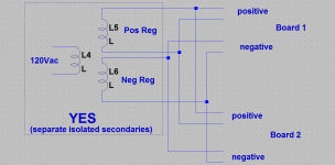
True, as long as the two board's outputs don't have anything in common, which they shouldn't (no common output ground). If the two boards do wind up with a common output ground you would need that quad isolated secondary transformer that PandazYa is using. Would be worth going through the wiring one more time and make sure everything goes to the right place.
I was actually thinking about the regulator on opc's new Wire power supply (which is negative). Looks like the LT1185 here can be wired either way, floating postive or grounded negative. I didn't know that! This wiring diagram still should be correct though, along with all the stuff about isolated secondaries.
Attachments
Last edited:
I have tested all 4 of my LPUHP's. They all check out ok. With the input shorted, 3 have 1mV of DC offset and the 4th one has 2 mV. Now I will temp hook 2 of them up to see if 15db is enough gain, may have to swap R8 for 21db.
I seem couldn't find TPS7A3301 in KC package in my country. Only QFN available. Shipping would cost a bomb from Digikey or Mouser.
Anyone generous enough to post a few pieces to Malaysia?
Payment could be made through Paypal.
Anyone generous enough to post a few pieces to Malaysia?
Payment could be made through Paypal.
Hey everyone, I just want to verify that this transformer is acceptable for The Wire PSU and BAL-BAL.
http://www.digikey.com/product-detail/en/70053K/1295-1028-ND/3881346
I understand the regs can handle 1 amp, but I'm not going to fry any resistors or anything if I decide to run my HE-6 headphones full blast? Thanks in advance.
http://www.digikey.com/product-detail/en/70053K/1295-1028-ND/3881346
I understand the regs can handle 1 amp, but I'm not going to fry any resistors or anything if I decide to run my HE-6 headphones full blast? Thanks in advance.
Last edited:
Hi Brunk,
That one should work.
Any of these would be fine too, and might be easier to implement:
Invalid Request
Regards,
Owen
That one should work.
Any of these would be fine too, and might be easier to implement:
Invalid Request
Regards,
Owen
Hi Brunk,
That one should work.
Any of these would be fine too, and might be easier to implement:
Invalid Request
Regards,
Owen
Thanks OPC for the confirmation. Looks like I'm in luck for wiring as I have some 18awg that fits the boards, which can easily handle 1 amp 🙂
One more question OPC, is it possible for the BAL-BAL to output 10w, or atleast 9w for the HE-6? I have run it off speaker amps with watt meters at max volume and am finding 10w peaks.
Last edited:
Not quite... maximum RMS current is 177mA, and maximum voltage is 22VRMS for a maximum power per channel of 3.9W into 125 ohms. That means an absolute maximum of 7.8W of output power per board.
All of these things coming together is exceedingly unlikely, but if you know you have 125 ohm power hungry headphones, then you probably should plan for a 15VA toroid as a minimum.
Generally speaking, I would use a 25VA for everything since they don't cost any more, aren't much larger, and will mean you're covered for power delivery no matter what.
Cheers,
Owen
Not quite... maximum RMS current is 177mA, and maximum voltage is 22VRMS for a maximum power per channel of 3.9W into 125 ohms. That means an absolute maximum of 7.8W of output power per board.
All of these things coming together is exceedingly unlikely, but if you know you have 125 ohm power hungry headphones, then you probably should plan for a 15VA toroid as a minimum.
Generally speaking, I would use a 25VA for everything since they don't cost any more, aren't much larger, and will mean you're covered for power delivery no matter what.
Cheers,
Owen
Thanks Owen, I too came to 7.8w output, but just wanted to verify from an experienced person as yourself. I suppose I can start trusting myself a little more now 🙂
I was actually thinking about the regulator on opc's new Wire power supply (which is negative). Looks like the LT1185 here can be wired either way, floating postive or grounded negative. I didn't know that! This wiring diagram still should be correct though, along with all the stuff about isolated secondaries.
That's how I connected both boards and heared hum. The regulators became warm immediatelly. I tried to switch the phase and the hum became louder and the regulator not warm but hot in few seconds.
Output GND is not connected between the boards.
That's how I connected both boards and heared hum. The regulators became warm immediatelly. I tried to switch the phase and the hum became louder and the regulator not warm but hot in few seconds.
Output GND is not connected between the boards.
Interesting! That sure sounds like it is wired correctly. Maybe I'm not understanding something about how it all wires up. 🙂 About the only other thing I could think of is some sort of common connection between the boards via mounting screws, since the boards work OK when powered individually.
Last edited:
When using a common transformer secondary pair, one cannot separate the audio grounds in a multichannel amplifier.
You need quad secondaries to give an isolated PSU for each of a two channel amplifier.
Then those two channels each need their respective Main Audio ground connected direct, or via a disconnecting network, to the Chassis for safety of the user/operator.
When one dual secondary is used, the two channels MUST SHARE the Main Audio Ground. The Speaker Returns MUST read zero ohms between each other.
What do you mean with Main Audio Ground? Shall ein center both output GND? Till now both amps had no connection and were mounted on a piece of wood, so there were just the primary windings, which were connected to the amps.
Main Audio Ground (MAG):
the location where all the audio circuits get their "ground" reference.
Usually we see signal ground and speaker ground and power ground and decoupling ground and Zobel ground and NFB ground and ..and...and..
all meeting at this physical point. These are NECESSARY parts of the audio circuits to allow proper operation.
Some call it star ground.
Some add on mains' Safety Earth. But this is NOT necessary for audio operation. It is an obligatory inconvenience that makes the system SAFE to use.
In my head/mind I see the MAG primarily as the necessary AUDIO GROUND that all analogue circuits require to operate.
I just wanted to use only one transformer for both boards, but one board is humming then.
I just re-read what you wrote here and realized that only one board hums when you power both from the single transformer, not both.
It would be interesting to take an AC voltage reading on the transformer secondary when it is powering just one board, then again when powering both boards.
Then, with both boards powered and the one board humming, AC voltage readings after the regulators from both V+ and V- rails to ground on both boards.
Just curious is somehow a regulator on the humming board is going into dropout, either due to load (resistive short) or a bad/damaged regulator not up to specs.
It will probably take opc to figure this one out! 🙂
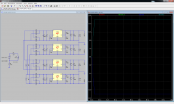
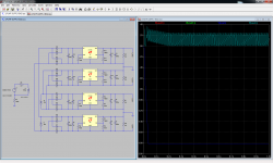
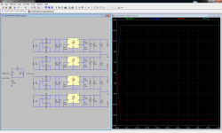
Attached are three simulations showing what should and should not work for the transformer connections.
It looks like using a single transformer might work, but you have to make sure the same winding is feeding the same regulator on each PCB (eg. Winding A feeds both positive regs and winding B feeds both negative regs)
I checked the simulated currents in all the windings, and they appear to be the same as with a fully isolated quad arrangement.
What you cannot do is use the same winding to feed both a positive and a negative reg. In this case, you get no output on the positive rail, just a large AC voltage.
I don't mean to scold Stammheim in any way, but I would ask in the future that if people plan to deviate from what is specified, in any way, that they only do it if they really know exactly what they are doing. Some things may seem like they are sure to work at a glance, but sometimes you really need to think it through before trying it.
If you're unsure, then simulate it, work it out, or ask for help before risking your boards and potentially your safety.
In this case, I don't think any permanent damage will have been done, but there are some arrangements that will cause permanent damage, and could cause the transformer to fail, which could cause a fire, and could be very serious.
Please be cautious!
Regards,
Owen
Attachments
Hi Owen,
I currently own a pair of AKG Q701 (Not balanced) and would like to know which head amp you could recommend for me?
I'm guessing “The Wire” SE-SE Headphone Amp ($15 for a single stereo board) + PSU
Thanks
Do
I currently own a pair of AKG Q701 (Not balanced) and would like to know which head amp you could recommend for me?
I'm guessing “The Wire” SE-SE Headphone Amp ($15 for a single stereo board) + PSU
Thanks
Do
Hi Do,
Since the AKG phones use a 3 pin detachable cord, there is no way to run them balanced without some serious modifications, so I would suggest going for the SE-SE and the new PSU.
Regards,
Owen
Since the AKG phones use a 3 pin detachable cord, there is no way to run them balanced without some serious modifications, so I would suggest going for the SE-SE and the new PSU.
Regards,
Owen
Hi Owen,
I currently own a pair of AKG Q701 (Not balanced) and would like to know which head amp you could recommend for me?
I'm guessing “The Wire” SE-SE Headphone Amp ($15 for a single stereo board) + PSU
Thanks
Do
Hello,
as I saw no reason, why both boards connected in the same way wouldn't work, I saw no reason why ask the forum. As there is hum I need to clarify if it's my soldering failure or something else. I'll make some measurements on the boards on weekend. I also wondered why there is -2.5mV DC in the output. I never had a minus value.
Just an addition to MAG... star ground is clear for me. As I plan three different kinds of amps in my config (LPUHP for tweeters, LME's fotr mid and class-d for subs) with three power supplies I decided not to take the LPUHP into the star ground because of the SMPS's I use. But I could use an own star ground for the LPUHP instead. You mean, this could help?
Last edited:
- Home
- Vendor's Bazaar
- "The Wire" Official Boards for All Projects Available Here! BAL-BAL, SE-SE, LPUHP