Hi Greg,
I was running off memory alone before, just had a bit of a dig myself to satisfy my own curiosity and here is what I found.
Mid November
Looking a bit further there was this post in late Oct:
So I do wonder if perhaps Owen has a few NTD1 boards he's just not comfortable selling, perhaps poke him gently and ask if you could buy one to butcher for the PSU section? 😀
Chris
I was running off memory alone before, just had a bit of a dig myself to satisfy my own curiosity and here is what I found.
Mid November
The only significant change is that the NTD1 boards have been removed from the order sheet, and I have noted those orders in a separate spreadsheet. I am doing some major rework on that circuit, and I don't want to sell people a bunch of boards and then release a brand new version a month later. I will deal with the NTD1 orders at a later time.
Looking a bit further there was this post in late Oct:
As a quick update, the NTD1 boards arrived yesterday, but there was a shipping mix up and the main panels with all the other boards won't be here until the end of this week.
So I do wonder if perhaps Owen has a few NTD1 boards he's just not comfortable selling, perhaps poke him gently and ask if you could buy one to butcher for the PSU section? 😀
Chris
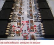
Here they are:
Check continuity between points A and B. You should see a short (near 0 ohms).
Check continuity between points A and C. They should be open circuit (several Mohms).
Check continuity between points B and C. They should be open circuit (several Mohms).
See picture below for points.
The thick bottom trace up the center of the board is the positive speaker output, and that is what got connected to the two V- pins of the decoupling caps and the LME49610.
These traces have been cut on everyone's boards, and I did measure each one to ensure it was done correctly, but please check carefully that you didn't accidentally short the cut with solder while soldering the two bypass caps near the cuts.
Regards,
Owen
Attachments
<SNIP>
The only significant change is that the NTD1 boards have been removed from the order sheet, and I have noted those orders in a separate spreadsheet. I am doing some major rework on that circuit, and I don't want to sell people a bunch of boards and then release a brand new version a month later. I will deal with the NTD1 orders at a later time.
<SNIP>
Thanks Chris, I missed that comment. Getting old!
And thanks for the suggestion. At this point, I'd rather wait and see the new reg circuits and see if I can hack them into the existing layout.
BTW and off-topic, around that post I saw the exchange between you and Owen about soldering the TPS7A4700 chips. I have several of the bare boards from Ian and about that time had access to a fine soldering station and a good microscope... that made all the difference in getting them soldered for me, I was getting pretty good by the time I got to the fourth and final.
Pity the EQ is no longer available!
Later!
Greg in Mississippi
Here they are:
Check continuity between points A and B. You should see a short (near 0 ohms).
Check continuity between points A and C. They should be open circuit (several Mohms).
Check continuity between points B and C. They should be open circuit (several Mohms).
See picture below for points.
The thick bottom trace up the center of the board is the positive speaker output, and that is what got connected to the two V- pins of the decoupling caps and the LME49610.
These traces have been cut on everyone's boards, and I did measure each one to ensure it was done correctly, but please check carefully that you didn't accidentally short the cut with solder while soldering the two bypass caps near the cuts.
Regards,
Owen
thanks i know all of mine are shorted b/c i used solder paste and a toaster to do the boards
Hi Owen and folks
just quick question, if I used AMB s22 PSU for these headphone amps, is it suitable? I know the size is very big compared to The Wire PSU design. Just want to use any available that ready to use before making another purchase to The Wire PSU (already buy old PSU parts but can't be used 🙁 )
just quick question, if I used AMB s22 PSU for these headphone amps, is it suitable? I know the size is very big compared to The Wire PSU design. Just want to use any available that ready to use before making another purchase to The Wire PSU (already buy old PSU parts but can't be used 🙁 )
Last edited:
I'm thinking about building one of these (BAL-Bal) but I'm curious if anyone has paired it with HD650s. Anyone?
Not with the BAL-BAL... I'm using the SE-SE with Senn' HD650s fed by either an ODAC or my old Pinoeer DV-757Ai. The HD650s perform admirably, loads of detail without being overly analytical 🙂
Just curious, why balanced with the HD650s?
Paul
Just curious, why balanced with the HD650s?
Paul
Not with the BAL-BAL... I'm using the SE-SE with Senn' HD650s fed by either an ODAC or my old Pinoeer DV-757Ai. The HD650s perform admirably, loads of detail without being overly analytical 🙂
Just curious, why balanced with the HD650s?
Paul
I think the real question is... why not? 😉 But seriously I've heard good things about balanced HD650s. I've never got to listen to them balanced though. My first pair of "good" cans were HD 650s about 6 years ago but they were unbalanced. If I build a BAL-BAL I can fulfill that dream and at a mighty fair price. The only worry is that I've never done SMD, plenty of through hole though.
Will report back after the repair. Thank you for the suggestion.Let us know what you find.
Does anyone have a LPUHP BOM for mouser?
I think the real question is... why not? 😉 But seriously I've heard good things about balanced HD650s. I've never got to listen to them balanced though. My first pair of "good" cans were HD 650s about 6 years ago but they were unbalanced. If I build a BAL-BAL I can fulfill that dream and at a mighty fair price. The only worry is that I've never done SMD, plenty of through hole though.
Then I say go for it 😀 SMD isn't as hard as it looks, just a touch more patience required... might try balanced one day 🙂
Keep the capacitors cool by not running the chip on high voltage supply rails.
My one runs too hot with +-59Vdc (40Vac)
Just about acceptable on +-50Vdc (35Vac)
Nice and cool on +-44Vdc. (30Vac)
My one runs too hot with +-59Vdc (40Vac)
Just about acceptable on +-50Vdc (35Vac)
Nice and cool on +-44Vdc. (30Vac)
Which 'chip' do you refer to AndrewT?
Paul, the headphone driver has no reference to ground, there is no need for the output to have a ground reference ... balanced output has only upsides and no downsides (once you have headphones wired for four terminal connection). The only time I'd use the SE-SE is if I had a source with SE output.
Paul, the headphone driver has no reference to ground, there is no need for the output to have a ground reference ... balanced output has only upsides and no downsides (once you have headphones wired for four terminal connection). The only time I'd use the SE-SE is if I had a source with SE output.
Which 'chip' do you refer to AndrewT?
Paul, the headphone driver has no reference to ground, there is no need for the output to have a ground reference ... balanced output has only upsides and no downsides (once you have headphones wired for four terminal connection). The only time I'd use the SE-SE is if I had a source with SE output.
I would second this ^
If your setup is balanced (or even if it will be eventually) the BAL-BAL would be my choice. Wiring a set of headphones for balanced operation is very easy as long as the stock cables were made properly with separate ground feeds back to the jack. All you need to do is buy a male and female in-line 4-pin XLR (about $6 worth of parts from Mouser), cut the existing cable leaving a 6" to 12" length of cable on the jack side, and solder in the new XLR cable.
This allows the headphones to be used with balanced or normal amplifiers, so you don't lose any compatibility.
Using Lemo connectors is even better, since they are smaller, and feel like a nice swiss watch every time you use them 🙂
You'll have to budget at least $75 for the Lemo parts though, if you can find them :S
Andrew:
What temperatures are you measuring on the caps themselves? Keep in mind that these are 105C 10,000 hour parts, so running the LME and the caps at even 80C is generally fine.
This also depends on the orientation of the board, and it's best to mount it sideways with the caps on the bottom.
Generally speaking, the build is easier (and everything runs cooler) if you stay with roughly +/-50V rails which still gives 250W into 4 ohms. I'm assuming that people who really want to push the limits, with +/-80 to +/-100V rails will either need larger heatsinks for the LME, or move to active cooling.
Cheers,
Owen
Cheers 🙂 I don't own a balanced source yet, so never properly looked at the in's & out's of it. That could be my next, next-project 🙂
Possibly a Twisted Pear COD & IVY III feeding a BAL-BAL > HD650s ... hmmm!
Possibly a Twisted Pear COD & IVY III feeding a BAL-BAL > HD650s ... hmmm!
Last edited:
Hey guys,
I finished my LPUHP's today and tried to activate them. Unfortunatelly only hum came out, about 100Hz I guess. Same problem with and without source. I tried both boards with same results, both are SE-assembled with the last BOM. Any failured I didn't read yet?
Thanks,
Stammheim
I finished my LPUHP's today and tried to activate them. Unfortunatelly only hum came out, about 100Hz I guess. Same problem with and without source. I tried both boards with same results, both are SE-assembled with the last BOM. Any failured I didn't read yet?
Thanks,
Stammheim
Last edited:
Hi Stammheim,
Even with no input they should be dead quiet, so there's a problem somewhere.
Can you post a picture of the top and bottom of the board around the front end?
I suspect there is a component missing somewhere.
Regards,
Owen
Even with no input they should be dead quiet, so there's a problem somewhere.
Can you post a picture of the top and bottom of the board around the front end?
I suspect there is a component missing somewhere.
Regards,
Owen
Here's a picture of the buttom, as there's not much to see on the front.
The more Ag into the solder... first and last time. So not really good looking...
The more Ag into the solder... first and last time. So not really good looking...
An externally hosted image should be here but it was not working when we last tested it.
- Home
- Vendor's Bazaar
- "The Wire" Official Boards for All Projects Available Here! BAL-BAL, SE-SE, LPUHP