You do understand that the circuit matters? 😀
Thank you.
Yes, I do.
I referred to what was presented.
If you look hard enough you can always get measurable components at any order. Some of them may be just noise; some of them may be FFT windowing artifacts. -100dB at a few volts out should be inconsequential for the first stage of a phone preamp. The danger of straining at gnats in electronic design is that you may end up swallowing a camel!
Thank you.
There are some camels nearby.
Perhaps I'll go to look for one.
Alas, I'm strict vegetarian, so I may leave the camel alone.
I would be very wary of sims predicting high-order distortion. They're reasonable for approximating 2nd, a little less good at 3rd, and not much good at all for higher terms.
Why? Different tubes from different vendors have different, and rather subtle, manufacturing errors. Although not visible to the eye, they have major effect on high-order distortion terms. In a tube as mundane as a 6SN7, I've seen variations of 20 dB for 5th-order (and higher) terms. The variations tend to be vendor-specific, which strongly points to differences in manufacturing. Vacuum tubes are not simple to build, and the famous tubes from the Golden Age sometimes used surprisingly exotic materials.
The most disappointing thing of all is the poor correlation to sonics. You'd think the tubes that have the lowest proportion of unwanted high-order harmonics would sound the best. Not always; in fact, I can't find any real correlation, except to weed out tubes that are obviously defective.
Where does this leave simulations? Well, it'll tell you if the circuit works (assuming the real-world circuit takes measures to avoid oscillation and instability). But I have to tell you that simulations don't tell you much about how it will sound. They can tell you if a driver is going to slew, which is bad, and can warn about instability, which is more than bad.
Allan Wright was a guest at my home for week after one of the Seattle-area VSAC shows. One of the things we disagreed about was the use of Tek vertical-amp scope circuits for audio. I worked at Tek, and the Tek old-time audio-builders didn't use scope circuits for audio. Those circuits were intended for scope displays, where nonlinearities of less than 2% simply aren't visible. Fast, yes, but not intended for linear applications. Ultrafast cascode circuits can be very difficult to stabilize; the actual scopes had little production-line tweaks all through the circuit to optimize pulse performance.
I'm sorry to be so discouraging. Designing a good RIAA preamp, particularly with tubes, is not easy. If I were you, if you want to go down the DIY path (which I encourage), I'd build this or that preamp exactly as designed, and decide whether you like it or not. It's a lot cheaper than wasting money on overpriced and underperforming audiophile preamps, and will quickly inform you which tubes and circuits you like. Some of us like the really old tubes, and others like the mid-Sixties exotics. Listen for yourself and draw your own conclusions.
Last edited:
Hi Lynn,
Thank you very much. I highly appreciate your response.
Indeed. I know that simulations are limited in many ways. Simulations cannot substitute actual measurements – and above all, listening evaluation.
This also my experience with tubes rolling in two preamps and a phono stage. Tubes having the same number, from different manufacturers, and from different manufacturing dates, sound entirely different from one another.
Yet, it is my conviction that, on top of that, choosing the right tube for any given circuit is of crucial importance.
I accept what you wrote, because of you have much more experience with tubes than I do. Actually, so far I didn't design any tube amp from scratch, so I lack the experience that you, and others here, have.
Yet, I wonder, because of in your article titled "The Amity, Raven, and Aurora" you wrote:
"Tubes that fit this application are the 5687/7044/7119 family or the Russian 6H30. (Although the familiar 6DJ8/6922/E88CC has low plate impedances, it also has moderately high third-harmonic distortion and limited output swing, which make it inappropriate for a PP DHT-triode amplifier.)"
---
"You might think that really old tubes - designs dating from the early Thirties - sound "vintage" and "tubey." Actually, they don't. Tubes in this family (27, 37, 56, 76, and 6P5) actually sound fast, quick, and incisive, and have very low distortion, along with a favorable distribution of harmonics. If you want a traditional mellow "vintage" sound, you're thinking of a 12AU7, the tube used almost universally in late 1950's amplifiers and many guitar amps - with distortion many times higher than the early Thirties tubes."
---
"It wasn't until the late Nineties that the space-age family (5687, 7044, 7119) and radio-age family (27, 37, 56, 76, 6P5) were re-discovered. It's not the looks, it's the performance. These triodes stand out for their low distortion and favorable distribution of harmonics, lower than any other type of analog device, pentode, bipolar transistor, JFET, or MOSFET. They sound good for a reason."
---
"Returning to direct-heated territory, Gary and I compared old-stock RCA 2A3's (might as well use the genuine article, right?) with old-stock 45's. Although 2nd and 3rd harmonic distortion levels were similar, the NOS 2A3 unfortunately had 5 to 10dB more of the 4th, 5th, 6th, 7th, 8th, and 9th harmonics than the 45 triode."
---
"It should be mentioned that the raw THD figure is quite misleading, since it is usually dominated by the 2nd harmonic, even in Class A PP circuits. 2nd harmonic, by itself, is nearly inaudible, since it is a full octave higher than the original musical spectra, and is musically consonant. Similarly, the 4th harmonic is two octaves higher, and is also musically consonant. But 3rd, 5th, 6th, 7th, and 9th are very dissonant and ugly sounding, and are easily heard, especially with increasing order. In the 1950's, both Norm Crowhurst and D.E.L. Shorter (of the BBC) proposed weighting harmonics by the square or cube root of the order to better reflect their audibility. Small amounts of high-order harmonics - even when 60 to 100 dB down - are musically significant."
---
"As medium-gain, medium-current triodes go, the 5687/7044/7119 familiy are one of the lower-distortion ones out there - but not in the same league as DHT power tubes. Are there any tubes with gains of 20 or more that have lower distortion than the 5687/7044/7119 group, particularly in the upper harmonics? Good question, since the 5687/7044/7119 group have a more favorable distribution of harmonics than most other medium-gain tubes."
---
"As far as I know, the 5687/7044/7119 family has the most favorable distribution of harmonics, along with a moderate Rp of 1500 ohms per plate in the 16 to 20mA operating region."
---
"1) Select active devices for minimum upper harmonic distortion. Although some devices have reasonably low second-harmonic distortion, the ear is not very sensitive to 2nd harmonic. It's the 3rd and higher-order harmonics that create unpleasant "electronic" colorations."
I don't know what to conclude from the combination of what you wrote here and what you wrote in what I quoted.
So far I didn't see a phono stage design that I'd like to make a copy of.
As difficult as it is, I do intend to design one.
However I need to reshuffle my cards and start again thinking and considering the topology and architecture I'd like to start with. I'd start a new thread about the various considerations and compromises.
What I have firm opinions about, at this stage, are the following:
1. Lowest possible noise (within the limits of the chosen architecture, which will be decided upon by other factors, along low noise).
2. Only transformers coupling.
3. Best linearity (within the limits of the chosen architecture, which will be decided upon by other factors, along linearity).
4. Lowest odd harmonics and higher harmonics distortion (within the limits of the chosen architecture, which will be decided upon by other factors, along distortion distribution).
5. Enough headroom.
I'd like to ask you a couple of questions about your Raven preamp (which may be relevant to my phono stage architecture considerations):
1. You chose differential pair, while differential pair reduce even harmonics and sum odd harmonics. Why did you choose differential pair? Is it because of the tubes family you chose have very low odd harmonics distortion to begin with?
2. Differential pair operates best with cathode CCS, yet you didn't use one. Why? Was it in order to save an additional, negative PSU?
Thank you.
Thank you very much. I highly appreciate your response.
I would be very wary of sims predicting high-order distortion. They're reasonable for approximating 2nd, a little less good at 3rd, and not much good at all for higher terms.
Indeed. I know that simulations are limited in many ways. Simulations cannot substitute actual measurements – and above all, listening evaluation.
Why? Different tubes from different vendors have different, and rather subtle, manufacturing errors. Although not visible to the eye, they have major effect on high-order distortion terms. In a tube as mundane as a 6SN7, I've seen variations of 20 dB for 5th-order (and higher) terms. The variations tend to be vendor-specific, which strongly points to differences in manufacturing. Vacuum tubes are not simple to build, and the famous tubes from the Golden Age sometimes used surprisingly exotic materials.
This also my experience with tubes rolling in two preamps and a phono stage. Tubes having the same number, from different manufacturers, and from different manufacturing dates, sound entirely different from one another.
Yet, it is my conviction that, on top of that, choosing the right tube for any given circuit is of crucial importance.
The most disappointing thing of all is the poor correlation to sonics. You'd think the tubes that have the lowest proportion of unwanted high-order harmonics would sound the best. Not always; in fact, I can't find any real correlation, except to weed out tubes that are obviously defective.
I accept what you wrote, because of you have much more experience with tubes than I do. Actually, so far I didn't design any tube amp from scratch, so I lack the experience that you, and others here, have.
Yet, I wonder, because of in your article titled "The Amity, Raven, and Aurora" you wrote:
"Tubes that fit this application are the 5687/7044/7119 family or the Russian 6H30. (Although the familiar 6DJ8/6922/E88CC has low plate impedances, it also has moderately high third-harmonic distortion and limited output swing, which make it inappropriate for a PP DHT-triode amplifier.)"
---
"You might think that really old tubes - designs dating from the early Thirties - sound "vintage" and "tubey." Actually, they don't. Tubes in this family (27, 37, 56, 76, and 6P5) actually sound fast, quick, and incisive, and have very low distortion, along with a favorable distribution of harmonics. If you want a traditional mellow "vintage" sound, you're thinking of a 12AU7, the tube used almost universally in late 1950's amplifiers and many guitar amps - with distortion many times higher than the early Thirties tubes."
---
"It wasn't until the late Nineties that the space-age family (5687, 7044, 7119) and radio-age family (27, 37, 56, 76, 6P5) were re-discovered. It's not the looks, it's the performance. These triodes stand out for their low distortion and favorable distribution of harmonics, lower than any other type of analog device, pentode, bipolar transistor, JFET, or MOSFET. They sound good for a reason."
---
"Returning to direct-heated territory, Gary and I compared old-stock RCA 2A3's (might as well use the genuine article, right?) with old-stock 45's. Although 2nd and 3rd harmonic distortion levels were similar, the NOS 2A3 unfortunately had 5 to 10dB more of the 4th, 5th, 6th, 7th, 8th, and 9th harmonics than the 45 triode."
---
"It should be mentioned that the raw THD figure is quite misleading, since it is usually dominated by the 2nd harmonic, even in Class A PP circuits. 2nd harmonic, by itself, is nearly inaudible, since it is a full octave higher than the original musical spectra, and is musically consonant. Similarly, the 4th harmonic is two octaves higher, and is also musically consonant. But 3rd, 5th, 6th, 7th, and 9th are very dissonant and ugly sounding, and are easily heard, especially with increasing order. In the 1950's, both Norm Crowhurst and D.E.L. Shorter (of the BBC) proposed weighting harmonics by the square or cube root of the order to better reflect their audibility. Small amounts of high-order harmonics - even when 60 to 100 dB down - are musically significant."
---
"As medium-gain, medium-current triodes go, the 5687/7044/7119 familiy are one of the lower-distortion ones out there - but not in the same league as DHT power tubes. Are there any tubes with gains of 20 or more that have lower distortion than the 5687/7044/7119 group, particularly in the upper harmonics? Good question, since the 5687/7044/7119 group have a more favorable distribution of harmonics than most other medium-gain tubes."
---
"As far as I know, the 5687/7044/7119 family has the most favorable distribution of harmonics, along with a moderate Rp of 1500 ohms per plate in the 16 to 20mA operating region."
---
"1) Select active devices for minimum upper harmonic distortion. Although some devices have reasonably low second-harmonic distortion, the ear is not very sensitive to 2nd harmonic. It's the 3rd and higher-order harmonics that create unpleasant "electronic" colorations."
I don't know what to conclude from the combination of what you wrote here and what you wrote in what I quoted.
I'm sorry to be so discouraging. Designing a good RIAA preamp, particularly with tubes, is not easy. If I were you, if you want to go down the DIY path (which I encourage), I'd build this or that preamp exactly as designed, and decide whether you like it or not. It's a lot cheaper than wasting money on overpriced and underperforming audiophile preamps, and will quickly inform you which tubes and circuits you like. Some of us like the really old tubes, and others like the mid-Sixties exotics. Listen for yourself and draw your own conclusions.
So far I didn't see a phono stage design that I'd like to make a copy of.
As difficult as it is, I do intend to design one.
However I need to reshuffle my cards and start again thinking and considering the topology and architecture I'd like to start with. I'd start a new thread about the various considerations and compromises.
What I have firm opinions about, at this stage, are the following:
1. Lowest possible noise (within the limits of the chosen architecture, which will be decided upon by other factors, along low noise).
2. Only transformers coupling.
3. Best linearity (within the limits of the chosen architecture, which will be decided upon by other factors, along linearity).
4. Lowest odd harmonics and higher harmonics distortion (within the limits of the chosen architecture, which will be decided upon by other factors, along distortion distribution).
5. Enough headroom.
I'd like to ask you a couple of questions about your Raven preamp (which may be relevant to my phono stage architecture considerations):
1. You chose differential pair, while differential pair reduce even harmonics and sum odd harmonics. Why did you choose differential pair? Is it because of the tubes family you chose have very low odd harmonics distortion to begin with?
2. Differential pair operates best with cathode CCS, yet you didn't use one. Why? Was it in order to save an additional, negative PSU?
Thank you.
I would not build a Raven today. It was Allan's visit, along with his PP 300B power amp, that turned me away from current-sourced differential circuits. I was able to compare his amp to the Karna, and I very strongly preferred my own amplifier. Allan's sounded very bass-shy, thin, and didn't have the headroom of the Karna amplifier, yet both amps used the same high-current Vaic DHT's on the output stage.
I consulted with Gary Pimm, my mentor on many of these things, and we came to the conclusion that current-sourced differential circuits don't have the peak current capability of Class A PP circuits. To explain: if both devices share a common current source, when one device goes all the way to one side and shuts off (infinite impedance), the most current the opposing device can draw is 2X the quiescent current. In other word, when one side current-clips, the whole circuit clips, since it is a series circuit.
By comparison, the two devices in a Class A PP circuit are in parallel, not series, so when one device shuts off, the other is free to conduct as much current as necessary. Since the usual quiescent bias for vacuum tubes is typically 1/5 to 1/10 of the peak current the cathode is capable of emitting, the other device is free to conduct much more current than the 2X limit of the current-sourced diff circuit.
And it sounds like that. My experience has been that current-sourced diff circuits sound thin, especially in power amplifiers, driver stages, or line amps that have to deliver power. More current delivery frequently results in warmer sound, more headroom, and less sense of stress.
Where does this lead a preamp? In my experience, they all sound different from each other, even when the RIAA equalization is precisely matched. Noise from the input stage is a common issue, although I'm more concerned about slewing induced by MC mistracking. Another gremlin is inability of the first or second stage to drive the reactive load of the RIAA network; tubes like the 12AX7, run at less than 1mA, are big culprits here, since they can't deliver linear current into the reactive load of the RIAA network, and are prone to slewing.
I don't know if Gary Pimm has posted his preamp circuit, but when I finally get my phonograph running, I'll almost certainly have him build one for me. I've heard it and it's a lot better than the preamps sold to the audiophile market.

Hi Lynn,
Thank you.
I wouldn't dream of using 12AX7, I know it's current driving limitation.
How about choosing only transformers loading to all tubes, both in phono stage and preamp?
BTW, I saw (probably on one of the forums here) a phono stage schematic by Gary Pimm, dated Dec. 12 2003. It uses his BBMCCS as load to both tubes. I wonder if transformers wouldn't do better.
Transformer loading is fine for the output tube, but I wouldn't use it anywhere else. If the preamp is a three-stage device with passive split-pole RIAA compensation, the capacitance loading on the first and second tubes has to be kept to an absolute minimum. That rules out transformers, which have 30~60 pF (at a guess) of stray capacitance. There are special audio-grade inductors (sometimes called reactors) which are optimized for low capacitance (on one end), and that might qualify for the second tube. Gary Pimm's current sources have well under 1 pF of load capacitance, have an voltage compliance of more than 100 volts, and are very linear.
One of the pitfalls of RIAA compensation is getting an exact phase match between channels. With a mono, pre-equalized RIAA test source, the output phase error between channels, from 50 Hz to 15 kHz, should be less than 5 degrees. You will have to hand-match the capacitors, and use 0.1% resistors, to achieve a phase-match this precise. If the left and right tubes have slightly different plate impedances, and the plate impedance forms part of the RIAA equalization network, this will have to be adjusted for.
One of the pitfalls of RIAA compensation is getting an exact phase match between channels. With a mono, pre-equalized RIAA test source, the output phase error between channels, from 50 Hz to 15 kHz, should be less than 5 degrees. You will have to hand-match the capacitors, and use 0.1% resistors, to achieve a phase-match this precise. If the left and right tubes have slightly different plate impedances, and the plate impedance forms part of the RIAA equalization network, this will have to be adjusted for.
Last edited:
I wouldn't dream of using 12AX7, I know it's current driving limitation.
You will never make a good enough (in comparison to what is achievable in general) preamp for MC cartridges with any other valve at the input either! In one case it will the noise, in another the drive capability and/or the gain and/or the microphony etc....
Most of the discussion around the ECC83 was about linearity anyway. I wouldn't use it either....
Your cascode idea using solid state devices at the input sounds good. In this application the 6922 works perfectly. You can make a simple and very effective hybrid cascode with a 2SC2240 at the bottom and the 6992 on top with a double switch (one that bypasses the transistor collector and goes into a normal cathode resistor and the other that goes from the transistor base into the 6992 grid, of course to be operated with the supply off) that will allow the 6992 to work as normal common cathode for MM use.
The split RIAA can be a good solution. The second stage has to have some gain (something in the D3a/ECC81 range). You need to look for those transistors though as soon as possible because now you can still find them but have been discontinued.... unfortunately!
Last edited:
Hi Joshua,
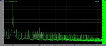
This is the (quick and dirty) breadboard measuring of C3g (C3g triode connected, B+: 400V, 18mA CCS anode load, 235R and 100uF in the cathode).
Input: Viktors 1kHz generator (0.0004% THD), inverse RIAA -40dB output, output level: 30mV RMS.
Measuring set: 100kOhm attenuator, EMU0404 USB, Visual Analyser, laptop.
As you can see, 50 and 100Hz harmonics are dominant below -90dB (no shielding).
C3g THD: 0.0186%
C3g harmonics: -75dB, -90dB, other no detectable (too much noise).
Attachments
euro21, interesting but for the relevance it would be interesting with a comparement with another tube, for example D3A in the same setup. Otherwise its hard to know what devise in the test setup that gives what result. Is that possible?
At 30mV output, you're probably measuring the distortion of the source. Take a look at the distortion spectrum of His Master's Noise, which uses a D3a at the input.
Again, in a phono stage, the distortion will be limited by the second stage, not the first, unless there's a severe design mistake.
Again, in a phono stage, the distortion will be limited by the second stage, not the first, unless there's a severe design mistake.
Hi Lynn,
Thank you.
Why 3 stage and not two?
Do you have example of such inductors?
Don't SS CCS ad coloration, as linear as they may be?
When this is the case, the RIAA compensation network should be trimmed whenever the tubes are being replaced. A bugger!
Thank you.
Transformer loading is fine for the output tube, but I wouldn't use it anywhere else. If the preamp is a three-stage device with passive split-pole RIAA compensation, the capacitance loading on the first and second tubes has to be kept to an absolute minimum.
Why 3 stage and not two?
That rules out transformers, which have 30~60 pF (at a guess) of stray capacitance. There are special audio-grade inductors (sometimes called reactors) which are optimized for low capacitance (on one end), and that might qualify for the second tube.
Do you have example of such inductors?
Gary Pimm's current sources have well under 1 pF of load capacitance, have an voltage compliance of more than 100 volts, and are very linear.
Don't SS CCS ad coloration, as linear as they may be?
One of the pitfalls of RIAA compensation is getting an exact phase match between channels. With a mono, pre-equalized RIAA test source, the output phase error between channels, from 50 Hz to 15 kHz, should be less than 5 degrees. You will have to hand-match the capacitors, and use 0.1% resistors, to achieve a phase-match this precise. If the left and right tubes have slightly different plate impedances, and the plate impedance forms part of the RIAA equalization network, this will have to be adjusted for.
When this is the case, the RIAA compensation network should be trimmed whenever the tubes are being replaced. A bugger!
Thank you.
I may build MM phono stage with step-up transformer for MC.
Why 2SC2240?
Aren't MAT03 good enough?
You will never make a good enough (in comparison to what is achievable in general) preamp for MC cartridges with any other valve at the input either!
I may build MM phono stage with step-up transformer for MC.
…
Your cascode idea using solid state devices at the input sounds good. In this application the 6922 works perfectly. You can make a simple and very effective hybrid cascode with a 2SC2240 at the bottom and the 6992 on top with a double switch (one that bypasses the transistor collector and goes into a normal cathode resistor and the other that goes from the transistor base into the 6992 grid, of course to be operated with the supply off) that will allow the 6992 to work as normal common cathode for MM use.
The split RIAA can be a good solution. The second stage has to have some gain (something in the D3a/ECC81 range). You need to look for those transistors though as soon as possible because now you can still find them but have been discontinued.... unfortunately!
Why 2SC2240?
Aren't MAT03 good enough?
I may build MM phono stage with step-up transformer for MC.
Two pieces of advice:
1. Take the opportunity to run your MC balanced.
2. Pay particular attention to the effects of loading on the secondary. This is almost certainly how SUTs got a bad reputation in certain circles; the effects of load were ignored, leading to ringing or premature rolloff.
Two pieces of advice:
1. Take the opportunity to run your MC balanced.
2. Pay particular attention to the effects of loading on the secondary. This is almost certainly how SUTs got a bad reputation in certain circles; the effects of load were ignored, leading to ringing or premature rolloff.
Thank you, SY.
Running the MC cartridge balanced is what I had in mind all along.
As for the secondary loading, experimenting with various loading values goes without saying for me. I thought of starting with a potentiometer, finding out the best value and installing fixed resistors.
All this will come at a later stage.
First I need to decode about the basic topology, or architecture.
At this point, I dropped off the ideas of cascoding, LTP and transformer loading the first stage.
I'm considering LCR RIAA equalization.
But before that, I need to consider the choice of tubes. At this point, I'm considering E810F for the first stage (because of its' low noise) and D3a for the second stage (because of its' linearity).
After choosing tubes and anodes loading, I'll have to see how to bias the tubes without NFB (no un-bypassed cathode resistor(s)) and without bypassing the cathode(s) resistor(s) with electrolytic capacitor(s) – which are in the signal path.
Isnt E810F a little highish on both Ri and anode-grid capacistance?
Edit. Ri triode connected is good, sorry.
Edit. Ri triode connected is good, sorry.
Last edited:
It's not just the resistive loading, since the tubes will have significant input capacitance- what you want to do is start with a resistor, vary it and see how it works. If you can't get a square wave through cleanly, substitute a series RC network and vary resistance and capacitance. See, for example, the 8055 page on Sowter's website, where Morgan Jones shows the effects of optimizing secondary loading.
Sowter Type 8055
You might want to read through the His Master's Noise article to get some ideas on biasing.
LCR is faddish, and I still have not seen a single justification on why replacing nearly ideal Rs and Cs with very non-ideal Ls is a good thing.
Sowter Type 8055
You might want to read through the His Master's Noise article to get some ideas on biasing.
LCR is faddish, and I still have not seen a single justification on why replacing nearly ideal Rs and Cs with very non-ideal Ls is a good thing.
Well you need to decide what you want first as a bjt could not be the best choice for MM input or at least it will not be the best for the circuit I told before. The noise figure changes quite a lot because of the different source impedance for sure. It works very well with low impedance sources like MC's.Thank you.
I may build MM phono stage with step-up transformer for MC.
Because I don't know the MAT03? The actual transistor is not really the point, there are some just as good. It is rather the type and its application.Why 2SC2240?
Aren't MAT03 good enough?
- Status
- Not open for further replies.
- Home
- Amplifiers
- Tubes / Valves
- C3g triode-strapped linearity question