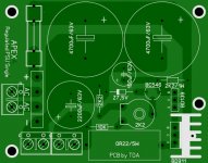
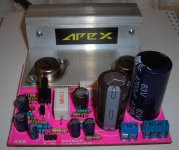
Willy please correct 10uF polarity on this pcb also 25mm diametar caps will be nice 🙂
dear sir,
can i use byv32 in place of byv36 because it is not availabe in my town.thanks
dear sir,
can i use byv32 in place of byv36 because it is not availabe in my town.thanks
Yes, use any TO220 dual diode.
I will report my progress. i modified your circuit as proposed in post #138 http://www.diyaudio.com/forums/solid-state/236256-retro-amp-50w-single-supply-14.html#post3651389 .
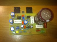
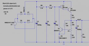
I made a new PCB based on the circuit i attach. comparing this with your original(but with mjl21194 as output and vbe multiplier included), i have to say that using 2sc5200 as outputs can unfold high frequency content better but in a tiring way.
On the contrary,MJL21194 are more relaxing and ''warm''.By the way,using MJL21194 as output at both your original circuit(vbe multiplier included) and at attached schematic below, your original feedback scheme sounded better to me.
So i m gonig back with post #129 design http://www.diyaudio.com/forums/solid-state/236256-retro-amp-50w-single-supply-13.html#post3649584 which is your original schematic plus a vbe multiplier and a signal,power,clipping indicator.
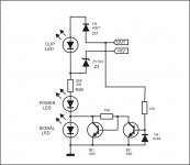
Do i have to change any values from this signal,power,clipping indicator from your AX20 to work with this retro AX6?
I made a new PCB based on the circuit i attach. comparing this with your original(but with mjl21194 as output and vbe multiplier included), i have to say that using 2sc5200 as outputs can unfold high frequency content better but in a tiring way.
On the contrary,MJL21194 are more relaxing and ''warm''.By the way,using MJL21194 as output at both your original circuit(vbe multiplier included) and at attached schematic below, your original feedback scheme sounded better to me.
So i m gonig back with post #129 design http://www.diyaudio.com/forums/solid-state/236256-retro-amp-50w-single-supply-13.html#post3649584 which is your original schematic plus a vbe multiplier and a signal,power,clipping indicator.
Do i have to change any values from this signal,power,clipping indicator from your AX20 to work with this retro AX6?
Attachments

Last edited:
I will report my progress. i modified your circuit as proposed in post #138 http://www.diyaudio.com/forums/solid-state/236256-retro-amp-50w-single-supply-14.html#post3651389 .
I made a new PCB based on the circuit i attach. comparing this with your original(but with mjl21194 as output and vbe multiplier included), i have to say that using 2sc5200 as outputs can unfold high frequency content better but in a tiring way.
On the contrary,MJL21194 are more relaxing and ''warm''.By the way,using MJL21194 as output at both your original circuit(vbe multiplier included) and at attached schematic below, your original feedback scheme sounded better to me.
So i m gonig back with post #129 design http://www.diyaudio.com/forums/solid-state/236256-retro-amp-50w-single-supply-13.html#post3649584 which is your original schematic plus a vbe multiplier and a signal,power,clipping indicator.
Do i have to change any values from this signal,power,clipping indicator from your AX20 to work with this retro AX6?
Nice work, use 3k3/1W instead 6k8/2W in clipping indicator.
Regards

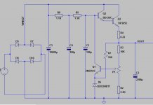
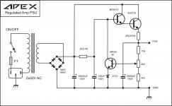
Thank you.I really like your amp.About your simple regulated psu for AX6 you posted,can it drive adequatelly 2 channels? I have a 2x24V ac transformer so i am planning to connect together the center cables so as to achive 48V ac. In your simple regulated psu for AX6 Ripple rejection can be improved by adding an extra resistor and an extra cappacitor.Thus,a second order filter is created which reduces the hum more effectively. What to you think?should i give it a try or stick to your original design ?
Attachments
Thank you.I really like your amp.About your simple regulated psu for AX6 you posted,can it drive adequatelly 2 channels? I have a 2x24V ac transformer so i am planning to connect together the center cables so as to achive 48V ac. In your simple regulated psu for AX6 Ripple rejection can be improved by adding an extra resistor and an extra cappacitor.Thus,a second order filter is created which reduces the hum more effectively. What to you think?should i give it a try or stick to your original design ?
Beter use capatience mutiplayer with this low rail voltage.
do you have any capacitance multiplier circuit using transistor?
You can made it from Regulated PSU.
Attachments
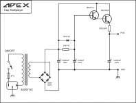
on the schematic above,a good place to put a fuse would be between 10000uF output capacitor and the amplifier or between bridge rectifier and 10000uF input capacitor?
on the schematic above,a good place to put a fuse would be between 10000uF output capacitor and the amplifier or between bridge rectifier and 10000uF input capacitor?
Put 2A fast fuse between 10000uF output capacitor and the amplifier
A fuse between the transformer and the main smoothing caps has to pass the capacitor charging current.
That fuse needs to be rated to pass very high current.
It becomes so big to survive start up that it never blows no matter how severe the abuse downstream.
The close rated mains fuse will blow long before the massively over rated secondary fuse
The fuse in the supply rail AFTER the main smoothing can be sized to suit your speakers.
Quasi and myself came up independantly of a very similar method.
eg.
for a 100W into 4ohms speaker the maximum continuous output is Iac (continuous) = sqrt(100W / 4r) = 5Aac = 7Apk
Quasi suggests the two rail fuses be 5/2 = 2.5A
AndrewT suggests the two rail fuses be 7/2 and be Fast type i.e F3.1A
The reason for dividing by 2 is because the duty cycle of the fuses is 50%. Each rail supplies speaker current for half the cycle of the AC waveform.
Short term transients into a reactive speaker due to musical peaks are able to pass these rail fuses without blowing. A F3.1A fuse will pass 10Apk and 15Apk and even 20Apk if the transient is short term.
BUT !!!!!!!!
You must check what happens at the output if ONE fuse blows.
Does the output rail go to +ve or -ve rail when one fuse passes power to the amplifier?
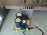
Very informative AndrewT. Thanks.In the case here,we are talking about a single supply PSU so no worry about the voltage at the output of the amp.My progress so far.Any comments for parts placement ,ground returns,and traces are welcomed...(some traces are aniqual in width but wiil be fixed.)
Attachments

Last edited:
- Home
- Amplifiers
- Solid State
- Retro Amp 50W Single Supply