wow! Willy you gave me goose bumps nice man I was practicing today with a Classic one Dx Blame ST
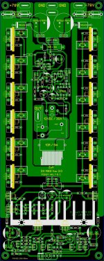
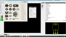
I never get tired of Carlos designs 🙂 here is a image I just stared today
I notice your skills are more nicer I like that brolet get some cold soda pops jejejejeje
hold on ????? that the B500 from mister Apex ? 😕 wow
Regards
Juan
Thanks bro...I just practicing the MKIII in different layout with protect onboard and will try to etch this one... if this design is good then later will try to add step driver and convert to class H hehehe...😀 just for fun...
Attachments
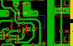
You have kept the +ve, -ve and Power Ground supplies close coupled, good.
You have rail to output diodes, good.
See if you can find space for rail to ground diodes. These should also be after the fuses.
Can you find room to fit HF decoupling (x7r, 100nF to 220nF) to each output device?
Maybe add a few MF decoupling per two pair of output devices.
Move your NFB tapping to the ACTUAL output trace. Even if you have to use a link to reach over that U shaped emitter resistor rail.
Thanks Drew appreciate your inputs....
The vu meter will flash like crazy add .47 on the input and ground and also an fast diode, if theres no diode and capacitor it will flash the damn leds.
With cap+diode it will be smooth.
It also needs pretty high input voltage swing, add opamp cheap crap like 358 or 4885
With cap+diode it will be smooth.
It also needs pretty high input voltage swing, add opamp cheap crap like 358 or 4885
good question
Yes I was wandering how mister Alex MM made those rounded traces? look nice and classic I like that 🙂
best regards
Juan
Alex how did you do the rounded traces on the first board shown in post #24?
Yes I was wandering how mister Alex MM made those rounded traces? look nice and classic I like that 🙂
best regards
Juan
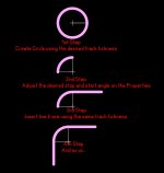
.... it's easy to draw , first layout circle and take only one arc from this circle , use also rotate function to stick different parts of arcs , and rest it's imagination 😉
Regards ,Alex
Regards ,Alex

You have rail to output diodes, good.
See if you can find space for rail to ground diodes. These should also be after the fuses.
The rail to output diodes are needed as the output stage employs current limiting, but why would rail to ground diodes be needed?
Last edited:
Dear Juan,
Can you post how to import images in jpg file in details the way how you created your scorpion and other logo.
Thanks in advance...
Can you post how to import images in jpg file in details the way how you created your scorpion and other logo.
Thanks in advance...
Two reasons that I know about.The rail to output diodes are needed as the output stage employs current limiting, but why would rail to ground diodes be needed?
1.) if you connect the PSU incorrectly or have miswired the PSU, the diodes turn on the light bulb in the tester or blow the mains fuse, if you have it close rated.
2.) if one supply rail fails, the diode on that rail prevents excessive reverse voltage on that rail until the other rail shuts down or you shut off the amplifier. That limit on reverse voltage prevents damage to electrolytic capacitors and semiconductors. And that is why I said
These should also be after the fuses.
Last edited:
Dear Juan,
Can you post how to import images in jpg file in details the way how you created your scorpion and other logo.
Thanks in advance...
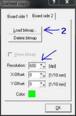
here are some example videos I did it quick 😀 the only thing you got yo do is take the image and change the format to BMP bimap then use "scanned copy
logos 1 - YouTube
logos 2 - YouTube
Regards
Juan
Attachments
Hello guys
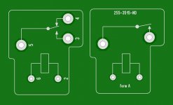
hey Willie when you get a chance can you compare this relay macros to the ones you have to see if I'm close to the correct size
Regards
Juan
hey Willie when you get a chance can you compare this relay macros to the ones you have to see if I'm close to the correct size
Regards
Juan
Attachments

Last edited:
here are some example videos I did it quick 😀 the only thing you got yo do is take the image and change the format to BMP bimap then use "scanned copy
logos 1 - YouTube
logos 2 - YouTube
Regards
Juan
Cool video dear Juan.. Thank you very much....
Hello guys
hey Willie when you get a chance can you compare this relay macros to the ones you have to see if I'm close to the correct size
Regards
Juan
Hi Juan copy that...
Hi Juan copy that...
I already send you the files to your e-mail so you can open it to see if I'm close "about" 😀
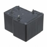
this image is the bottom DigiKey part number 255-3515-ND manufacture part number
JTN1AS-PA-F-DC15V
best regards
Juan
Attachments
Last edited:
I already send you the files to your e-mail so you can open it to see if I'm close "about" 😀
this image is the bottom DigiKey part number 255-3515-ND manufacture part number
JTN1AS-PA-F-DC15V
best regards
Juan
Done bro... have adjusted the pitch and the case and it is now accurate.... check your mail and let me know...
The 2.1mm dia holes are far bigger than the pins on my version of these relays. Potter and Brumfield T9AS1D12-24
One rattles around in 1.5 dia. the other needs 1.6 dia.
I would expect 1.7+-0.1mm dia to fit any T9AS
One rattles around in 1.5 dia. the other needs 1.6 dia.
I would expect 1.7+-0.1mm dia to fit any T9AS
multi-pitch macros
So many parts , a massive macro database.
Some devices , such as standard metal film .25-.50W - standard macro.
Caps - 3.5,5,7.5mm ... standard.
Same with semiconductors - JEDEC standard.
Relays and other proprietary components - some reuse E-waste relays ,
or use "buyouts"/surplus.
I do this for big capacitors ... some here buy Apex JR's caps, some buy
panasonics or Nichicon's from Mouser.
My PS "big cap" macro (10/22mm) fits em' all.
Custom "Sanken" to-264 macro??? DIY'ers use anything they have available.
I do admit , they look really good. Commercial products -YES ,DIY... overkill.
Also , old diy'ers (me too 😀) need bold screen-prints/large pads to even see
the work.
OS
Last edited:
- Status
- Not open for further replies.
- Home
- Amplifiers
- Solid State
- Dx Juan layouts ideas PCB