With 6 in ports you will be at 50 to 70 m/s airspeed when pushing 65 volts rms. Too small - maybe qnty 4 x 6 in ports? But that will affect response at lower power. If you are driving say 24 volts, you are at between 15 and 25 m/s - still a bit high - but that is 115 dB and near the verge of pain. 6 in is probably fine for most uses in a car.
If you don't need the flat response, the smaller 6 cu ft x 2 cu ft option should work. Also, I have no idea what a car's interior box does - suppose it could be modeled with Edge?
If you don't need the flat response, the smaller 6 cu ft x 2 cu ft option should work. Also, I have no idea what a car's interior box does - suppose it could be modeled with Edge?
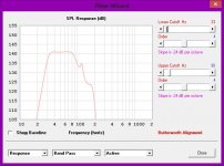
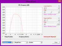
Yes, what tuning and airspace did you use for the smaller high tuned chamber in your design? It looks to be a good response curve at the higher end of the bandpass. The lower tuned chamber at 4 cubic feet is a hair small. With cabin gain applied I find a 6db rise below 40hz down to 25hz is appropriate. As I said, the car has a peak at 25hz, so really between 40-30 is where I need the majority of that gain. I'm sure somewhere around 7 cubic feet at 25hz fits the bill. Flat on an RTA doesn't sound flat when you in the confines of a vehicle, took SQ guys in car audio many years to figure this out sadly.
The literature on car lift shows + 12dB/Oct starting at 55 Hz. This is an average of may vehicles but all are individually close. The article is "Breaking Wind" by David Clark.
3 Cu ft and 1 Cu ft should work great. I have built and measured the response of one of these systems and the measurement is very very close to the BassBox simulation.
Measuring this system in your car accurately and correctly will be problematic. You want to be in the far field of the ports and you cannot do that in a car. You will be measuring the near field response.
With 6 in ports you will be at 50 to 70 m/s airspeed when pushing 65 volts rms. Too small - maybe qnty 4 x 6 in ports? But that will affect response at lower power. If you are driving say 24 volts, you are at between 15 and 25 m/s - still a bit high - but that is 115 dB and near the verge of pain. 6 in is probably fine for most uses in a car.
If you don't need the flat response, the smaller 6 cu ft x 2 cu ft option should work. Also, I have no idea what a car's interior box does - suppose it could be modeled with Edge?
I have enough width for 3 aero ports, not 4. How would three do? Say at 24, 48 and 65 volts? Just trying to get an idea. If not I'll have to mess around with a very tall and large slot port.
OP,
This software (Bass Box Pro software) seems to be reasonable good and accurate for the cabin gain in case you want to run it (same results).
It gave the same results as my calculations if I remember correctly, look at initial post#1 (from OP) and at my post#7, so they must be very close to reality (room/cabin gain).
http://www.diyaudio.com/forums/subwoofers/235466-box-2x10-woofers.html#post3492811
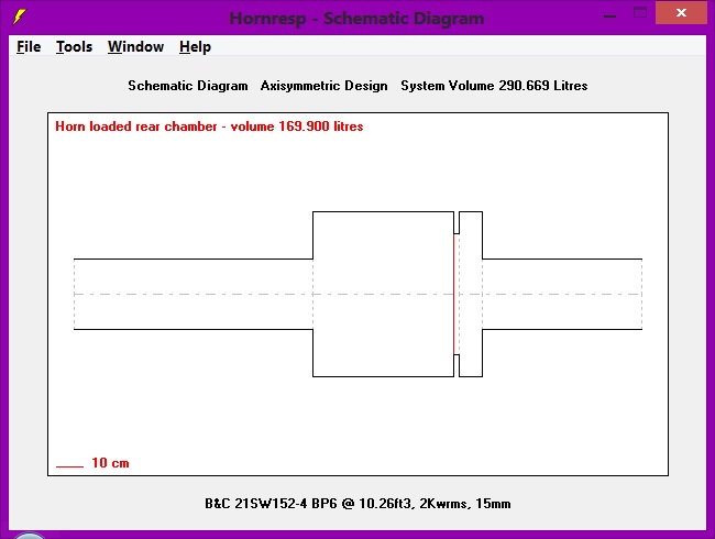
You need to include port volume with box volume.
V front = 1ft3.
V front port = 1.26ft3.
V rear = 6ft3.
V rear port = 1.89ft3.
V speaker plate = 0.11ft3 (0.75" stock).
V total = 10.26ft3.
V front = 1ft3.
V front port = 1.26ft3.
V rear = 6ft3.
V rear port = 1.89ft3.
V speaker plate = 0.11ft3 (0.75" stock).
V total = 10.26ft3.
Attachments
BP1Fan,
Is this how you are modeling 6th order bandpasses in HR? Those are awfully long ports that will need to fit in the box - almost will be folded horns?
X
Is this how you are modeling 6th order bandpasses in HR? Those are awfully long ports that will need to fit in the box - almost will be folded horns?
X
That's one way of modeling a bp6 enclosure in HR. The ports are a little more than 1/3 of Sd to prevent port noise at maximum volume.
6.85 cu ft box with qnty 8 x 5 in drivers (Buyouts)
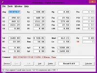
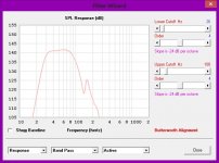
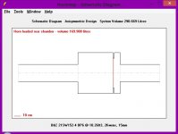
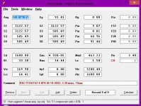
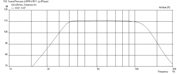
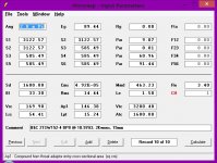
I stuck some blow out PE sub drivers into the 6th order bandpass design and got some interesting results. These are the $15 Tang Band W5-867SE's (16 ohms) so they are good for multi driver setups. I am running 8 drivers in parallel/series to get nominal 8 ohm. They have 5 mm xmax so the SPL will be limited. Here is the result of a 175L rear chamber tuned to 31Hz with 8 in vent and 19L front chamber tuned to 81Hz with 6 in dia vent. This is with a 29Hz high pass and 120Hz low pass filter. There is also a trick of 0.28 in dia hole drilled between the two chambers as a tuned 'leak' to help de-Q the chambers to flatten the response (something that is easy to do in Akabak).
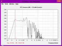
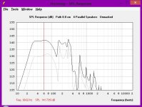
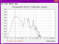
Here is the SPL at xmax.

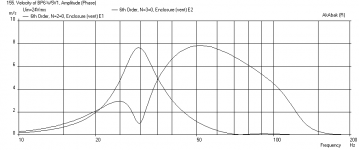
Here is port velocities at max SPL

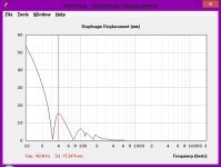
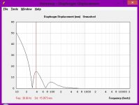
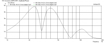
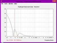
Here is cone excursion at max SPL

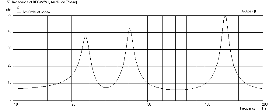
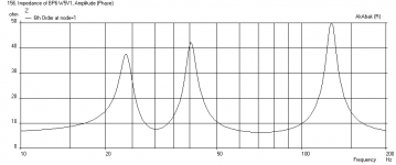
Here is Impedance
I stuck some blow out PE sub drivers into the 6th order bandpass design and got some interesting results. These are the $15 Tang Band W5-867SE's (16 ohms) so they are good for multi driver setups. I am running 8 drivers in parallel/series to get nominal 8 ohm. They have 5 mm xmax so the SPL will be limited. Here is the result of a 175L rear chamber tuned to 31Hz with 8 in vent and 19L front chamber tuned to 81Hz with 6 in dia vent. This is with a 29Hz high pass and 120Hz low pass filter. There is also a trick of 0.28 in dia hole drilled between the two chambers as a tuned 'leak' to help de-Q the chambers to flatten the response (something that is easy to do in Akabak).
Here is the SPL at xmax.
Here is port velocities at max SPL
Here is cone excursion at max SPL
Here is Impedance
Attachments
Last edited:
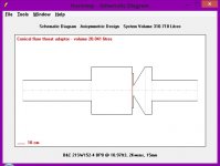
The enclosure would look similar to this.
An externally hosted image should be here but it was not working when we last tested it.
I stuck some blow out PE sub drivers into the 6th order bandpass design and got some interesting results. These are the $15 Tang Band W5-867SE's (16 ohms) so they are good for multi driver setups. I am running 8 drivers in parallel/series to get nominal 8 ohm. They have 5 mm xmax so the SPL will be limited. Here is the result of a 175L rear chamber tuned to 31Hz with 8 in vent and 19L front chamber tuned to 81Hz with 6 in dia vent. This is with a 29Hz high pass and 120Hz low pass filter. There is also a trick of 0.28 in dia hole drilled between the two chambers as a tuned 'leak' to help de-Q the chambers to flatten the response (something that is easy to do in Akabak).
Here is the SPL at xmax.
Here is port velocities at max SPL
Here is cone excursion at max SPL
Here is Impedance
I just read about that trick on Brian Steele's website regarding his P.O.C. TH.
Are the two port volumes included in that 6.85ft3?
Yes, the total volume is the combined. I took the hole drilling trick to extreme and turned a long horn into a 'flute' like pipe. It can flatten a lot of problems at the expense of extension and efficiency. Check out the 'flute pipe TL' thread in the full range forum if you are I interested. I am new to designing subs so would appreciate feedback as to whether or not this design is good/not good and how it compares to current designs out there.
You are an Akabak beast! I recall seeing inside pics of one of Tom Danley's early TH enclosures where he had used pvc tubes mounted to the speaker plate to tame peaks. I'm guessing you guys are going past 6th order in those situations. I think it's possible to model in HR by using the Ap1 and Lpt fields in the CH (compound horn) function.
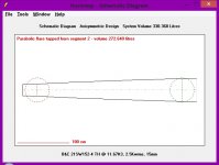
Here is my attempt in trying to convert the 10.26ft3 BP6 into a BP8. HR doesn't have enough segments to change that conical flare into a parabolic tube. To be a true BP8, I think that tube needs to be mounted in the rear chamber firing into the front chamber like the enclosure below.
Attachments
Last edited:
The enclosure would look similar to this.

Hi,
How do you imagine the front loading has anything to do with
a defined airspace loaded by a vent ? Simulation gone mad....
If you think this is modeled correctly :
You have a lot to learn about simulator assumptions. The above
is all wrong in many respects for a basic 6th order bandpass sub.
rgds, sreten.
With driver Vas of 7cuft and its Qts, anything suggesting a rear
volume above 7cuft is simply wrong, unless you want peaks.
Last edited:
The area directly in front of the woofer would be the 1ft3 chamber. The next area would be the 4.13" wide x 22" tall x 24" long port.
Did you read the OP's post, he wants a peak at 60hz! Also, here is a build where the front port volume is greater than front chamber volume.
IXL-18.2.2 Bandpass - Home Theater Forum and Systems - HomeTheaterShack.com
IXL-18.2.2 Bandpass - Home Theater Forum and Systems - HomeTheaterShack.com
What FACTS do you have that says the model is wrong for the OP's application. Until the enclosure is built, measured, and compared to the simulation, your OPINION don't count.
- Status
- Not open for further replies.
- Home
- Loudspeakers
- Subwoofers
- Anyone who can model 6th orders feel like helping?