Trying to build a 6th order bandpass for a B&C21sw152-4. I guess to start, everyone should know this WILL be going in a car. I came here because I know there are very good designers here who have access to good programs, unlike most car audio guys, I DO trust modelling lol.
Anyway I want to try a 6th order using passive radiators. I know with my cabin gain, approx 8cubes at 32hz will give me a audibly flat response down to around 25hz. At least in the octave of 50-25. (car's tend to need a good bit extra down low to sound flat) I also know I have a sharp spike in bass around 50hz and down low at 25 (hence why I can tune at 32 and be flat to 25). I dont' want to cut 50hz too much tbh, I'd rather the notch in my bandpass response center closer to 45hz, although if it took a bit at 50 I wouldn't complain. The top end needs to get to 80hz, no more. I'd like a little bump in response around 60hz, as I literally need to JUST get to 80hz. I will cross somewhere between 60-80hz at 24db/octave. I have plenty of space. If someone can give me some airpspace and tuning numbers that'd be great. As I said bottom end i can play with due to the adjustable passives, but I'm pretty sure 8@32hz is the ticket for getting the bass correct as possible below 40hz. Above that is where I really need help.
Anyway I want to try a 6th order using passive radiators. I know with my cabin gain, approx 8cubes at 32hz will give me a audibly flat response down to around 25hz. At least in the octave of 50-25. (car's tend to need a good bit extra down low to sound flat) I also know I have a sharp spike in bass around 50hz and down low at 25 (hence why I can tune at 32 and be flat to 25). I dont' want to cut 50hz too much tbh, I'd rather the notch in my bandpass response center closer to 45hz, although if it took a bit at 50 I wouldn't complain. The top end needs to get to 80hz, no more. I'd like a little bump in response around 60hz, as I literally need to JUST get to 80hz. I will cross somewhere between 60-80hz at 24db/octave. I have plenty of space. If someone can give me some airpspace and tuning numbers that'd be great. As I said bottom end i can play with due to the adjustable passives, but I'm pretty sure 8@32hz is the ticket for getting the bass correct as possible below 40hz. Above that is where I really need help.
Trying to build a 6th order bandpass for a B&C21sw152-4. I guess to start, everyone should know this WILL be going in a car. I came here because I know there are very good designers here who have access to good programs, unlike most car audio guys, I DO trust modelling lol.
Anyway I want to try a 6th order using passive radiators. I know with my cabin gain, approx 8cubes at 32hz will give me a audibly flat response down to around 25hz. At least in the octave of 50-25. (car's tend to need a good bit extra down low to sound flat) I also know I have a sharp spike in bass around 50hz and down low at 25 (hence why I can tune at 32 and be flat to 25). I dont' want to cut 50hz too much tbh, I'd rather the notch in my bandpass response center closer to 45hz, although if it took a bit at 50 I wouldn't complain. The top end needs to get to 80hz, no more. I'd like a little bump in response around 60hz, as I literally need to JUST get to 80hz. I will cross somewhere between 60-80hz at 24db/octave. I have plenty of space. If someone can give me some airpspace and tuning numbers that'd be great. As I said bottom end i can play with due to the adjustable passives, but I'm pretty sure 8@32hz is the ticket for getting the bass correct as possible below 40hz. Above that is where I really need help.
As far as I know there is not a simulation program that uses passive radiators for a series tuned bandpass.
Your best bet is to use BassBox to design a standard bandpass and then try to adjust the passive radiators to match the simulated impedance curve of the simulated bandpass with ports.
The series tuned bandpass is touchy to tune and is sensitive to errors in T/S parameters and mis-tuning of the box/ports.
If you don't have a WT2 and BassBox it will be difficult to make anything other than a whistle or a muffle.
FWIW, I don't think a conventional 6th order BP is "series-tuned" - that implies a port between the two chambers, which 6th order BPs don't have.
Its possible to convert between ports and passive radiators - there are calculators online that'll help you do this.
If you set off with the PRs mounted inverted (ie, masses visible), you'll be able to adjust them so that you get the correct impedance curve, which ought to give similar output to what the simulations would suggest for a ported (instead of PR) box. Turn them around when you're done, try one more impedance sweep to make sure, and job's a good 'un.
Chris
Hi,
I had a quick play with the driver in WinISD. 6cuft rear tuned to
26Hz and 2cuft front tuned to 60Hz produces a decent curve.
Try it, just plug in Qts, Fs and Vas of the driver.
Why ? because by changing the tunings you can see how
incredibly sensitive the response curve is to exact tunings.
Consequently I don't remotely trust the numbers WinISD
produces and would cross check them in other programs.
I do trust the effects of varying the tunings it shows.
What PR's do you intend to use ? How many and how ?
rgds, sreten.
32Hz rear tuning produces a large peak, try it yourself.
Last edited:
If you are making a standard acoustimass parallel tuned bandpass then you can use bassbox to design the system with ports. You could then model each side individually with bassbox to design the passive radiators.
This would be a parallel bandpass, not series tuned. The rear chamber on the bottom will be passives and the top section which the active woofer fires into from below it will be a slot port. I can also keep my passives facing the standard way. They are the exodus audio 15inch PR's that have the weight right behind the dust cap, simply unscrew and add weight 🙂 Think of it as a cube with the sub on top, 2 passives facing the rear of the vehicle and one on the left and right sides. Then set the top on it, which is the slot port and it's airspace, slot facing the rear, so in the end it will look like 2 15's with a slot port above them.
I realize 32hz tuning seems to produce a large peak in WINISD (I modeled that before I built it), but in the car, it doesn't seem all that pronounced. My current box for fun was 10cubes net at 30hz, and honestly I still have more output at 25hz than I do anywhere else below 50hz including near tuning. The car has quite a bit of gain at 25hz and more in the 40-50hz range than it does in the 30hz area, hence a peak in the mid to low 30's ends up filling in that gap. Perhaps if I shrunk it way down to 6cubes I could tune lower, I'll look into it, I can always add mass inside the box to lose some airspace once it's built. Also it seems a 6-10db rise as I go from 40-30hz tends to sound more flat in a small vehicle. Even in a home I like a 2-3db rise when I can get it in my lowest usable octave. The 10 cube box is just overall too much (duh) so I figured if I shrink the airspace down a bit, I should be about where I need to be. I can always mess with tuning later I find it doesn't work as I think it will.
I realize 32hz tuning seems to produce a large peak in WINISD (I modeled that before I built it), but in the car, it doesn't seem all that pronounced. My current box for fun was 10cubes net at 30hz, and honestly I still have more output at 25hz than I do anywhere else below 50hz including near tuning. The car has quite a bit of gain at 25hz and more in the 40-50hz range than it does in the 30hz area, hence a peak in the mid to low 30's ends up filling in that gap. Perhaps if I shrunk it way down to 6cubes I could tune lower, I'll look into it, I can always add mass inside the box to lose some airspace once it's built. Also it seems a 6-10db rise as I go from 40-30hz tends to sound more flat in a small vehicle. Even in a home I like a 2-3db rise when I can get it in my lowest usable octave. The 10 cube box is just overall too much (duh) so I figured if I shrink the airspace down a bit, I should be about where I need to be. I can always mess with tuning later I find it doesn't work as I think it will.
Last edited:
If you are making a standard acoustimass parallel tuned bandpass then you can use bassbox to design the system with ports. You could then model each side individually with bassbox to design the passive radiators.
That's kinda the part I needed the help with. Bassbox isnt' free ( to my knowledge) and all I have is WINSID, which I dont' trust for this in terms of getting some actual concrete starting points. Data-bass has extracted T/S parameters and B&C is generally known for very good build quality and unit to unit consistency.
Qts 0.326Qes 0.34Qms 7.94Fs 36.8Hz Res 3.4 ΩLe 1khz 1.84 mH Sd0.16m2 Vas146.5L Mms455.4g Cms41μm/N SplSens95.17 dB
With cabin gain of the vehicle on top of everything it's very hard to design anything perfect first try without simply building and testing, but I'd like to be in the ballpark of the response I want first try, I can always clean it up a bit with an EQ in the end anyways. ( I have a audessey style processor, but for the car, but It has a manual adjustment too)
Last edited:
Fire up Hornresp.
Click Add, which will give you a new page, and then Edit.
Mouse over all the labels for the variables, double-click to change them.
Here are the things to enter:
S1 = 1547, S2 = 1547, Con = 9
S2 = 1547, S3 = 156, Con = 0.1
S3 = 156, S4 = 156, Con = 10.
<driver parameters here - double click in the text-box to get help calculating>
Vrc = 80, Ap = 156, Vtc = 0
Lrc = 33, Lpt = 30
Those parameters are an approximation of an old Tannoy T40 cabinet that I happen to have - its a 1x15" 6th order bandpass cabinet, for PA use.
After you've typed all those in, hit Calculate.
Then change back to Input Parameters (under the Window menu at the top).
Next up, Tools > Loudspeaker Wizard.
Change the bottom-left drop-down to Response, and then the bottom-right drop-down to Combined.
You can then use the middle drop-down menu to access different sliders to change your cabinet, environment, drive voltage, etc etc.
Select Schematic (bottom-left drop-down) to see what you're building.
HTH, and feel free to ask any questions.
Chris
What do you mean by six or eight "cubes"? A bandpass of any order is easy to simulate in AkAbak - the trick is getting initial volumes and port dia and lengths close enough to start tweaking. For that you need some theory on 6th order bandpass alignments or an initial design somewhere that is close to what you want. Passive radiators can also be implemented.
What do you mean by six or eight "cubes"? A bandpass of any order is easy to simulate in AkAbak - the trick is getting initial volumes and port dia and lengths close enough to start tweaking. For that you need some theory on 6th order bandpass alignments or an initial design somewhere that is close to what you want. Passive radiators can also be implemented.
Cubic feet 🙂 If anyones willing to use akabak that would be GREAT as I know that's a tricky program and much appreciated. The box need a rising response ABOVE 50hz to combat my cabin gain.
The cabin gain is 1/2 the slope of the vented box rolloff. You will always have a hump or a stair step response curve. I have run boat loads of simulations and a closed box is the only alignment that can give a flat response without a hump or a stair step in your bass passband.
12.72 cu ft Box
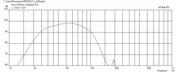
Here is what I came up with that addresses your requirements for:
- a flat to 25 Hz bottom end
- 80 Hz upper end
- a 'bump' at 60 hz (+3 dB in this case)
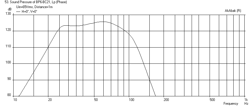
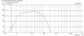
It will require a 12.72 cubic foot box (10.6 cu ft in front chamber, 2.12 cu ft in rear chamber). I used 6 in diam vents in both chambers. Tune the front chamber for 26 Hz, the rear chamber for 62 Hz. Use a -12dB/oct Butterworth high pass and -48dB/oct Butterworth low pass to limit excursion on low end and HF junk on high end. I used 6 in dia ducts initially but you will need larger ones (like 10 or 12 in dia equivalent or rectangular slots) if you want to keep port velocities smaller at peak SPL when pushing a kW.
Here is SPL vs Freq at 2.83V and 1m (matches the drivers efficiency rating from 25 Hz to 80 Hz):

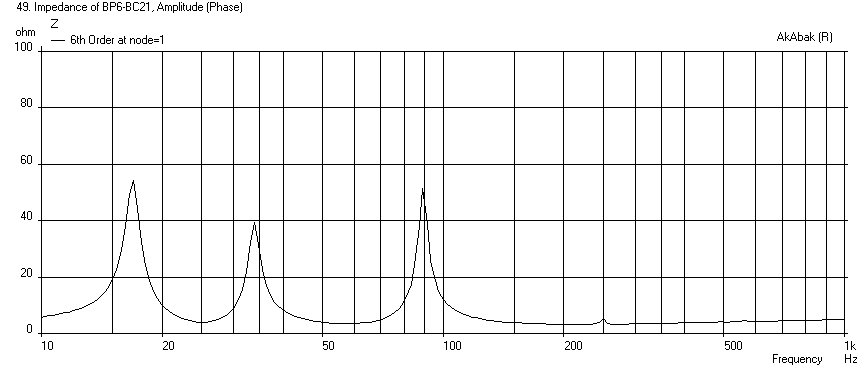
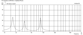
Here is the Impedance:
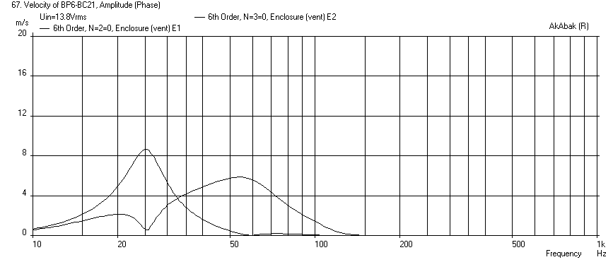
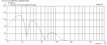
Here is max cone displacement at 65 volts rms:

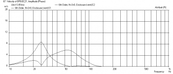
Here is corresponding max SPL at 65 volts rms (assuming no power compression effects).
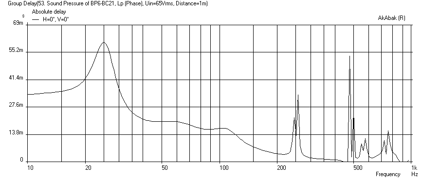
You get some wicked group delay below 40 Hz though - a problem with typical BP designs.
For a car, I guess 13.8 volts is max possible voltage? In that case, use 8 in dia ports and the velocities will be under 10 m/s
Regards,
X
Here is the script if you want to play with it.
Here is what I came up with that addresses your requirements for:
- a flat to 25 Hz bottom end
- 80 Hz upper end
- a 'bump' at 60 hz (+3 dB in this case)
It will require a 12.72 cubic foot box (10.6 cu ft in front chamber, 2.12 cu ft in rear chamber). I used 6 in diam vents in both chambers. Tune the front chamber for 26 Hz, the rear chamber for 62 Hz. Use a -12dB/oct Butterworth high pass and -48dB/oct Butterworth low pass to limit excursion on low end and HF junk on high end. I used 6 in dia ducts initially but you will need larger ones (like 10 or 12 in dia equivalent or rectangular slots) if you want to keep port velocities smaller at peak SPL when pushing a kW.
Here is SPL vs Freq at 2.83V and 1m (matches the drivers efficiency rating from 25 Hz to 80 Hz):
Here is the Impedance:
Here is max cone displacement at 65 volts rms:
Here is corresponding max SPL at 65 volts rms (assuming no power compression effects).
You get some wicked group delay below 40 Hz though - a problem with typical BP designs.
For a car, I guess 13.8 volts is max possible voltage? In that case, use 8 in dia ports and the velocities will be under 10 m/s
Regards,
X
Here is the script if you want to play with it.
Code:
| Vented 6th order Bandpass Cabinet
| XRK971
| Nov 1, 2013

Def_Driver  'BC21'
  Sd=1680cm2
  fs=32Hz
  Qms=7.00
  Qes=0.31
  Re=3.4ohm
  Le=1.5mH
  Bl=32.5Tm
  Vas=198L
  Mms=460g


Filter 'HighPass' |Highpass filter - 12dB/oct Butterworth
fo=20Hz vo=1
{b2=1;
a2=1; a1=2*0.707; a0=1; }

Filter 'LowPass' |Lowpass filter - 48dB/oct Butterworth
fo=110Hz vo=1
{b0=1;
a8=1; a7=5.125831; a6=13.137071; a5=21.846151; a4=25.688356; a3=21.846151; a2=13.137071; a1=5.125831; a0=1; }


System '6th Order BP'

  Driver 'Subwoofer'  Def='BC21'
    Node=1=0=2=3

|Vented enclosure at front
Enclosure  'E1'  Node=2
    Vb=300L  Qb/fo=1.0  Lb=70cm
    fb=26Hz  dD=6in
    x=0  y=40cm  z=0

|Vented enclosure at reverse
Enclosure  'E2'  Node=3
    Vb=60L  Qb/fo=1.0  Lb=30cm
    fb=62Hz  dD=6in
    x=0  y=-40cm  z=0
Attachments


Last edited:
Hi,
Strange that I get an almost identical curve to xrk971
In WinISD with the rear 6cuft/26Hz, front 2cuft/60Hz.
Going to 63Hz adds a dB or so to the upper bump.
12cuft is too big for a driver with a Vas of 7cuft, and
creates a large lower peak in WinISD with 26Hz tuning.
8cuft tuned to 22Hz also works for the rear in WinISD.
rgds, sreten.
Last edited:
When I plug in Sreten's values, the curve doesn't look as flat as above and efficiency is slightly lower, but could be passable and certainly more compact (the OP said size was not an issue though). Perhaps it is because Akabak is accounting for the internal chamber max dimensions (assumed to be 70 cm for the large and 30 cm for the small) and that the ports are separated by 80 cm and then combine in space to form the response at 1m? But this is my first time doing a BP design so I could just be wrong... I can try simulating it more rigorously with actual rectangular prisms of finite size, ducts placed in finite locations and orientations, etc.
Attachments
Thanks very much for that. What kind of airspeed am I dealing with if I use a 6inch vent? If I run it across the box it will be around 30inches wide and 6 high. As I mentioned, I will only be using a standard port on the higher tuned side.
My other option is to use aeroports, which can lower the airspeed quite a bit. If I did that I'd use dual aero's for visual purposes, as one large one wouldn't look as nice as 2 smaller ones and should perform similarly. It would probably be 2 6inch aeroports. how would they compare to a simple slot port?
Anyway voltage isn't really limited to 14 volts as that's the voltage at the battery, voltage at the amp and being delivered to the speaker would be an entirely different scenario. Your 65v simulation was accurate.
The sim you just modeled was very close to a designs someone on anther forum pointed me to. I think I will start with a the higher chamber very close to what you have designed and I can always shorten if needed, I'm sure I won't ever need to tune lower than that in any case. I almost wonder if a slightly larger or higher tuned vent would be more appropriate. I'm sure a rising response or even a flat response between 60-80hz would end up being closer to acoustically flat response when placed in the vehicle.
Anyway once I get the vent sized figured out it'll be off to the races with this thing and I can start getting some blueprints ready, very excited 😀
Edit: Also looking at your graph of 6@26HZ for the lower tuned chamber, with cabin gain that is also certainly passable, so I probably don't need to go with a full 12 cubic feet as that WOULD begin to be a stretch space wise. (my current box is around that external, and I could only go bigger by going taller, which my bandpass design MUST be anyway) I think somewhere in the middle where I originally proposed based on my known cabin acoustics will suffice.. Perhaps 7.5@28hz. I think that should give sufficient low end when cabin gain is taken into consideration.
Last edited:
12 ft^3 is way more than needed. I did it with 4 cu ft and took into consideration the cabin gain.
The cabin gain can be seen by the asymmetric rolloff of high vs low.
The cabin gain can be seen by the asymmetric rolloff of high vs low.
12 ft^3 is way more than needed. I did it with 4 cu ft and took into consideration the cabin gain.
The cabin gain can be seen by the asymmetric rolloff of high vs low.
Yes, what tuning and airspace did you use for the smaller high tuned chamber in your design? It looks to be a good response curve at the higher end of the bandpass. The lower tuned chamber at 4 cubic feet is a hair small. With cabin gain applied I find a 6db rise below 40hz down to 25hz is appropriate. As I said, the car has a peak at 25hz, so really between 40-30 is where I need the majority of that gain. I'm sure somewhere around 7 cubic feet at 25hz fits the bill. Flat on an RTA doesn't sound flat when you in the confines of a vehicle, took SQ guys in car audio many years to figure this out sadly.
Last edited:
- Status
- Not open for further replies.
- Home
- Loudspeakers
- Subwoofers
- Anyone who can model 6th orders feel like helping?