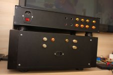
FC-100
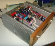
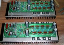
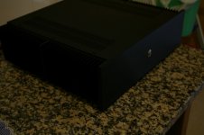
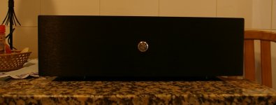
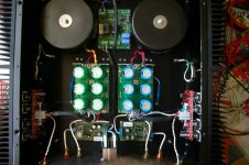
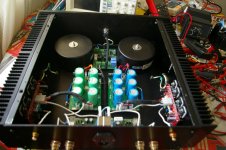
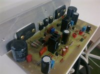
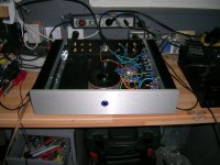
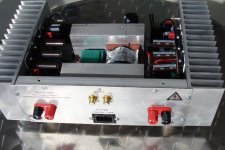
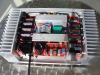
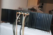
Gentlemen, let me show you the current progress of my FC-100 (originated by ROENDER) integrated amplifier (shown on the image below).
Everything that you see on this picture has been DIY'ed:
- the FC-100 amplifier -and shunt - PCBs (PCB layouts done by myself)
- the passive versatile, comfortable VCPre pre-amplifier, being based upon LDRs (PCB layout done by myself)
- Soft-Power-On and Speaker Protection (PCB layout done by myself)
- the aluminium case itself (with a little bit help of my friends)
- the wooden front (with a little bit help of my friends)
This is a true integrated amplifier and it sounds like a gem.
But it has been a long way to get until there and cost a lot of blood, sweat and tears.
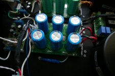
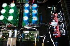
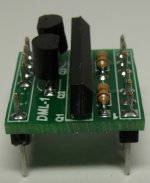
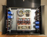
For example: the AK - PCB power connector (indicated by the left pink arrow) is real "Schrott" (rubbish) in my eyes.
Without noticing you will break the connection between the screw on top of the case and its solder pin, if you tighten it too much.
Even a small BOURNS potentiometer (indicated by the pink arrow on the right side) will loose and change its contact, once you will move your case a little bit.
Do you imagine, what it means, if this trimm-pot is involved in adjusting the bias current?
It will cause some serious thermal runaway - problems that you are not aware of, once you have moved / pushed the amplifier's case.
It is the mechanical problems that is paid too little attentiom in this forum and that will cost much "Blood, Sweat and Tears" to any un-experienced DIYer.
Best regards - Rudi_Ratlos
Gentlemen, let me show you the current progress of my FC-100 (originated by ROENDER) integrated amplifier (shown on the image below).
Everything that you see on this picture has been DIY'ed:
- the FC-100 amplifier -and shunt - PCBs (PCB layouts done by myself)
- the passive versatile, comfortable VCPre pre-amplifier, being based upon LDRs (PCB layout done by myself)
- Soft-Power-On and Speaker Protection (PCB layout done by myself)
- the aluminium case itself (with a little bit help of my friends)
- the wooden front (with a little bit help of my friends)
This is a true integrated amplifier and it sounds like a gem.
But it has been a long way to get until there and cost a lot of blood, sweat and tears.
For example: the AK - PCB power connector (indicated by the left pink arrow) is real "Schrott" (rubbish) in my eyes.
Without noticing you will break the connection between the screw on top of the case and its solder pin, if you tighten it too much.
Even a small BOURNS potentiometer (indicated by the pink arrow on the right side) will loose and change its contact, once you will move your case a little bit.
Do you imagine, what it means, if this trimm-pot is involved in adjusting the bias current?
It will cause some serious thermal runaway - problems that you are not aware of, once you have moved / pushed the amplifier's case.
It is the mechanical problems that is paid too little attentiom in this forum and that will cost much "Blood, Sweat and Tears" to any un-experienced DIYer.
Best regards - Rudi_Ratlos
Attachments
Last edited:
Thank you mhouston, it was a dead walnut tree on our yard 🙂
yes you right twister looks a bit like tenor and upside like consonance opera cd player.
yes you right twister looks a bit like tenor and upside like consonance opera cd player.
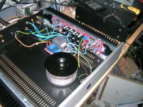
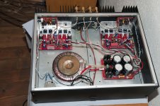
My SKA GB150D built with Jim's Audio pcbs:
Amp pcb's: Jim's Audio
Power Supply: HackerCap
Softstart: Sjostrom Audio
Speaker Protection: some kit from eBay
Transformers: 2 x300VA 35-0-35V
Amp pcb's: Jim's Audio
Power Supply: HackerCap
Softstart: Sjostrom Audio
Speaker Protection: some kit from eBay
Transformers: 2 x300VA 35-0-35V
Attachments
-
 IMGP8529.JPG314.2 KB · Views: 482
 -
 IMGP8528.JPG178.4 KB · Views: 343
 -
 IMGP8517.JPG252.1 KB · Views: 395
 -
 IMGP8509.JPG186.2 KB · Views: 430
 -
 IMGP8498.JPG284.8 KB · Views: 465
 -
 IMGP8495.JPG333.5 KB · Views: 598
 -
 IMGP8494.JPG354.3 KB · Views: 764
 -
 IMGP8491.jpg501.8 KB · Views: 1,724
 -
 IMGP8481.jpg304.6 KB · Views: 1,765
 -
 IMGP8555.JPG222.5 KB · Views: 1,966
Last edited:
Hi Paulo,
Nice work.🙂. Now you owe us feedback on the SYMEF thread.😀
kind regards,
Harrison.
Nice work.🙂. Now you owe us feedback on the SYMEF thread.😀
kind regards,
Harrison.
My SKA GB150D built with Jim's Audio pcbs:
Amp pcb's: Jim's Audio
Power Supply: HackerCap
Softstart: Sjostrom Audio
Speaker Protection: some kit from eBay
Transformers: 2 x300VA 35-0-35V
My SKA GB150D built with Jim's Audio pcbs:
Amp pcb's: Jim's Audio
Power Supply: HackerCap
Softstart: Sjostrom Audio
Speaker Protection: some kit from eBay
Transformers: 2 x300VA 35-0-35V
Very neat build, good work.
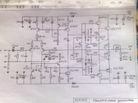
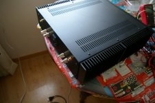
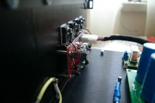
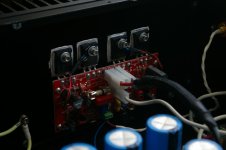
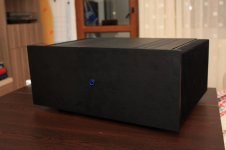
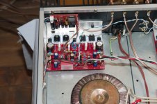
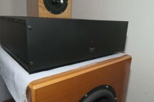
My FC-100
Finalized this summer with great support from Rudi and Mihai Rauta the creator itself.
Preamp consists of DCB1 and VcPre attenuator based on lightspeed.
Finalized this summer with great support from Rudi and Mihai Rauta the creator itself.
Preamp consists of DCB1 and VcPre attenuator based on lightspeed.
Attachments
Hugh is a friend of mine and member of the Melbourne audio club. How would you describe the sound of the amp?Naksa 80
Hugh is a friend of mine and member of the Melbourne audio club. How would you describe the sound of the amp?
Take a look at the Aksa thread there you can follow a review of mine and others regarding the Naksa 80
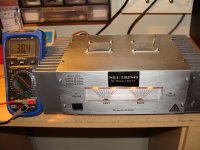
NEUTRINO. LME49810 with 3 paire transistors in output stag
Everything that you see on these pictures has been DIY'ed:
-Amplifier based on LME49810 power amplifier driver. (PCB layouts done by myself).
Output stage-3 pairs matched NJW4281 & NJW4302 ON semi.
-The power source is a full-bridge power converter based on ETD49 core.
+/-60Vcc 800W. (PCB layouts done by myself)
- The aluminum case done by myself.
Very easy to work with this LME driver and the sound astonish in a pleasant way.
Unfortunately, I made a mistake with inscription from front panel.
Clip left is repeat twice. This is it.
Attachments

My SKA GB150D built with Jim's Audio pcbs:
As much as i dig your green/blue cap colour scheme, whats the reason for it?

New thread for Spookydd amplifier here,
http://www.diyaudio.com/forums/solid-state/245032-work-progress-leach-based-amplifier.html
New thread for Spookydd amplifier here,
http://www.diyaudio.com/forums/solid-state/245032-work-progress-leach-based-amplifier.html
Cool! So I don't even need to start the new thread myself 🙂
- Home
- Amplifiers
- Solid State
- Post your Solid State pics here