Not to confuse the issue for other people, but I found it difficult to adjust the offset below +/-10 mV, or keep it there, with normal temp changes. At least in my case, adjustment using the trimpots is very sensitive, a small fraction of a turn seems to change the offset by a large amount.
In all my cases output DC offset was set to +/-1mV without any problem, and it stays there no matter the temp.
Trimmers are indeed sensistive but with gentle rotation the goal to set DC offset to 0 mV is achievable.

Please, make rails and offset measurements voltages with reference of your measuring instruments always at the ground point of the board. And a load.
Because the two boards behave the same, VAS currents OK, quiescent current Ok, the problem is probably on your measurements side, not on the board ones.
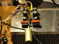
Please, try to measure voltage at the CSS out, (point common to the 47 Ohms, the 2200µF caps and the 10µF ones).
I measured 0.647V at CSS out.
Rails voltages before 22R +/-46V, after 22R as they enter the board +/-41.7V.
Regards
Marko
Hi again Marko, small shoots easy/quick to do.
Measure R17 should read 604R, and check solder each end have connection down trace (belongs to TLVH431 Network).
Measure R18 should read 1K, and check solder each end have connection down trace (belongs to TLVH431 Network).
Solder pads for TR3 got connection all three ?
Should input be shorted ?.
Guess you can regulate at TR3 i.e. get lover than 3,6V over 22R ?.
BC550C/BC560C, KSA1381/KSC3503 reversed ?
Regards Ricky
Hello Ricky,
R17, R18 measure as you said, continuity to nearest components OK.
TR3 measure 1K at the end of counterclockwise position, fully clockwise zero ohm for my current bias settings.
Maybe I should quit before probe slip🙄, if I remember 150mV was output bias "sweet spot" at the beginning.
Regards
Marko
Rails voltages before 22R +/-46V, after 22R as they enter the board +/-41.7V.
Regards
Marko
That is 4,3 V diff, meaning 195 mA of output bias, which is even over desired 180 mA. 🙂
That is 4,3 V diff, meaning 195 mA of output bias, which is even over desired 180 mA. 🙂
Sorry I should have been more precise, +/-45.7V before 22R, so I am back to 3.7V unfortunately.
Regards
Marko
Attachments
![IMG_0662[1].jpg](/community/data/attachments/338/338014-2835ab17317647bc44570a1c2a4c3549.jpg?hash=KDWrFzF2R7)
Last edited:
Than do as instructed in post #2660
I will do so, thank you Lazy.
Regards
Marko
Hi O.A.
After sending out last shipment I stil have 16 VSSA PCB sets on the stock. But these are really the last ones, so if anyone interersted ...
Best regards, L.C.
BTW very nice speakers you've made

Interested in 4 more PCBs, as written also via email. This has become an addiction, I know... 😀
Cheers!
I'm In!!
Hi Andrej and fellow VSSA dudes!
I believe in fate and it looks like our projects are aligned ...Just as you have the last few VSSA boards available, I need some!
Please put me down for 5 boards.
Is there a GB list or is it best to email you ( Andrej) directly?
One important technical question please!
Re power supplies for active speaker use in an " off the grid" battery powered system.
I have access to large capacity Li Po4 batteries at OEM prices and my entire system ( source, digital conversion and amps) is battery powered.
I can get almost any voltage from 3 volts up to 120 volts with current capacity up to 60 AmpH...What would you recommend as the best voltage / current capacity?
Thanks in advance and also thanks for your kind words re my loudspeakers!
Cheers
Derek.
Hi O.A.
After sending out last shipment I stil have 16 VSSA PCB sets on the stock. But these are really the last ones, so if anyone interersted ...
Best regards, L.C.
BTW very nice speakers you've made
Hi Andrej and fellow VSSA dudes!
I believe in fate and it looks like our projects are aligned ...Just as you have the last few VSSA boards available, I need some!
Please put me down for 5 boards.
Is there a GB list or is it best to email you ( Andrej) directly?
One important technical question please!
Re power supplies for active speaker use in an " off the grid" battery powered system.
I have access to large capacity Li Po4 batteries at OEM prices and my entire system ( source, digital conversion and amps) is battery powered.
I can get almost any voltage from 3 volts up to 120 volts with current capacity up to 60 AmpH...What would you recommend as the best voltage / current capacity?
Thanks in advance and also thanks for your kind words re my loudspeakers!
Cheers
Derek.
Hi O.A.
Are you sure for 5 boards, not 6? Just checking it is not a mistake.
I would suggest +/-45 V supply voltage.
For order please send me an e-mail with exact address and forum name to:
esl@siol.net
Best regards, L.C.
Are you sure for 5 boards, not 6? Just checking it is not a mistake.
I would suggest +/-45 V supply voltage.
For order please send me an e-mail with exact address and forum name to:
esl@siol.net
Best regards, L.C.
5 boards is good!
Thanks LC,
5 boards is good, stereo fronts, stereo rear and a centre channel.
If you develop a 1 Kw version I will buy two of them for the subs....!
I will order this afternoon to your email...On a train at the moment so signal poor.
Thanks
Derek.
Thanks LC,
5 boards is good, stereo fronts, stereo rear and a centre channel.
If you develop a 1 Kw version I will buy two of them for the subs....!
I will order this afternoon to your email...On a train at the moment so signal poor.
Thanks
Derek.
Here i understand VSSA match is intended for mentioned system setup......Now match that with the attached and you should have a marriage made in heaven....The group delay performance of this BMR line array is astonishing...
With no crossover, active or passive and only some Eq applied at source ( JRiver from a Lap Top) and no correction networks the 16 BMR drivers launch a totally coherent "cylinder of sound" into the room...I have been looking for an amp like yours for a few years.
LC can we talk about another commercial venture??!
Hi Derek, is it OK i get 😕 by your two posts takes very different angel on speaker setup and purpose for amps. Have nice train trip.Thanks LC,
5 boards is good, stereo fronts, stereo rear and a centre channel.
If you develop a 1 Kw version I will buy two of them for the subs....!
I will order this afternoon to your email...On a train at the moment so signal poor.
Thanks
Derek.
Last edited:
Success
Hi Lazy Cat,
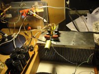
I did per your instructions, output bias is spot on at 4V, with plenty room to spare😀 Offset slightly went up, but that should be easy to solve.
Thanks again
Marko
On the top of R18 (1k) solder one 4,7 k the same size SMD resistor (both parallel) and you will get desired Iout bias. It looks like TR3 doesn't goes to zero resistance, so the parallel resistor to R18 will help to solve the problem. 😉
Hi Lazy Cat,
I did per your instructions, output bias is spot on at 4V, with plenty room to spare😀 Offset slightly went up, but that should be easy to solve.
Thanks again
Marko
Attachments
![IMG_0667[1].jpg](/community/data/attachments/338/338219-a6dc106a8a32b5713ed25253d8712b2d.jpg?hash=ptwQaooytX)
Off Grid VSSA...Yea!
Thanks LC,
+ /- 45 volts it is!
Thanks BYRTT, glad to hear you think the speakers / amp match is a good one!
By the way, as speaker guy I am not going to tackle this amp build myself so I am now looking for a UK based electronics guy to assemble these into 5 little mono block cases....I pay cash!!
Cheers
Derek.
I'll try it again.In all my cases output DC offset was set to +/-1mV without any problem, and it stays there no matter the temp.
Trimmers are indeed sensistive but with gentle rotation the goal to set DC offset to 0 mV is achievable.
Is it possible that I am at the end of the adjustment range for the trimmer? Nothing was changed or replaced on the boards so far. Everything else, bias etc. seems as it should be, all directions seem clear and easy to follow, supply voltage well below 45, sound excellent.
Dear LC,
Last night I finally had the time to test amp n°1. Very easy to follow instructions. I achieved 0,5mV offset at 160mA. Sounded excellent even with test PS.
Many thanks and how many kits do you still have?
Could I have two more, for my little brother? 🙂
Thanks again for your efforts and for sharing.
PS: I will try to figure out how to add trimmer Rs to DIY VSSA, just in case...
Attachments
Hello LCHi O.A.
After sending out last shipment I stil have 16 VSSA PCB sets on the stock. But these are really the last ones, so if anyone interersted ...
Best regards, L.C.
BTW very nice speakers you've made
I will do 4 more VSSA pcb sets. I want to do a line array with 1 PCB per speaker.
Lazy Cat,
I just wanted to make sure that you finally received the money for the two boards I wanted to try. I didn't hear anything but just thought that I would wait. Let me know if you did or didn't get the funding in the Paypal account. It would have said it was from Sabrina Soibelman my wife as it was her Paypal account. Can't send you any PM's as your mailbox is full
Thanks,
Steven Soibelman
kindhornman
.....Can't send you any PM's as your mailbox is full
.....
 .....?
Hi can this help, i seen many times members complaining they can't communicate via Andrej's mailbox at diy-site. This member mailbox has a limit of messages (relative small) but is free and needs owner to keep it under that limit.
Take a look in Andrej's posts that he want's to communicate via esl@siol.net, this domain site probably his own and i guess has no message limits, try it instead.
.....🙂Order sent
Hi LC,
Just confirming I sent my order yesterday to your personal email as requested.
Cheers
Derek.
Hi LC,
Just confirming I sent my order yesterday to your personal email as requested.
Cheers
Derek.
- Home
- Vendor's Bazaar
- VSSA Lateral MosFet Amplifier