Not to confuse the issue for other people, but I found it difficult to adjust the offset below +/-10 mV, or keep it there, with normal temp changes. At least in my case, adjustment using the trimpots is very sensitive, a small fraction of a turn seems to change the offset by a large amount.... Anything less than 5mV of total output offset whatever temp changes will be OK.
Please, make rails and offset measurements voltages with reference of your measuring instruments always at the ground point of the board. And a load.but I want to solve this output bias issues first
Because the two boards behave the same, VAS currents OK, quiescent current Ok, the problem is probably on your measurements side, not on the board ones.
Please, try to measure voltage at the CSS out, (point common to the 47 Ohms, the 2200µF caps and the 10µF ones).
Please, make rails and offset measurements voltages with reference of your measuring instruments always at the ground point of the board. And a load.
Because the two boards behave the same, VAS currents OK, quiescent current Ok, the problem is probably on your measurements side, not on the board ones.
Please, try to measure voltage at the CSS out, (point common to the 47 Ohms, the 2200µF caps and the 10µF ones).
I agree with you, everything is OK with quiescent current almost OK.
I have a question which is probably stupid, is it possible that my test heat sinks are inadequate even for amplifier idling and that some kind of thermal protection of alf mosfet is limiting me to raise the bias higher.
Regards
Marko
Don't seem so, see this link http://www.diyaudio.com/forums/vend...lateral-mosfet-amplifier-146.html#post3527045 from post #1456 where member are using old harddisk house. 😱.....is it possible that my test heat sinks are inadequate even for amplifier idling and that some kind of thermal protection of alf mosfet is limiting me to raise the bias higher.
Regards
Marko
Last edited:
Don't seem so, see this link http://www.diyaudio.com/forums/vend...lateral-mosfet-amplifier-146.html#post3527045 from post #1456 where member are using old harddisk house. 😱
Thanks Byrtt,
I would prefer positive answer, lets hope that the proverb morning is wiser than evening is true😀
BTW your skill to extract important info from topics is exemplary.
Regards
Marko
Hi Pete i will report when i fire up because you mentioned this before. Andrej reports in start of thread than he pair all components as he did in amp before VSSA to third or fourt digit on his fluke, if he also match devices this is answer to Andrej's nice spec in this area, also his own first boards were the one with fixed resistors instead of variable.Not to confuse the issue for other people, but I found it difficult to adjust the offset below +/-10 mV, or keep it there, with normal temp changes. At least in my case, adjustment using the trimpots is very sensitive, a small fraction of a turn seems to change the offset by a large amount.
I ordered 0,1% resistors for R5/R6 dual feedback 1K resistors, but the 8 times VSSA from Andrej has same precision as the one i ordered measured with my old relative cheap DMM. Maybe exchanging TR1/2/3 on your boards to fixed versions would help, but AGH!!! there's no space for this operation. Have you checked your R5/R6 for matching ?
Last edited:
mkusan, there is something i don't understand. Of course, you have understood that the two trimpots in input adjust both VAS bias, and general offset. Your VAS currents are equal and of a correct value. This is impossible if you had adjusted the bias by turning one of them to act on the bias. Are-you full resistance value in one of them and 0 for the other ?
Thanks, in reality not so hard to do. Hit botton "Go advanced" when posting or qouting because there you have "Preview Post" bottom to check your layout and if links is alive or dead. Example of the one with the HDD-case: that i find on another Explorer Tab, hit the post number in right side of the post, this hit updates the address bar field in top of Explore, then copy this long data in adress bar field to your text (looks like mess), check by hitting "Preview Post" botton and things get nice in preview. Also in "Go advanced" mode Pictures/files can be loaded to this sites server instead of a link to your personal cloud services, which if you change them then link in post is dead and looks dead and cold......BTW your skill to extract important info from topics is exemplary.....
I have not replaced any parts. I have just the one pair of modules, and experimenting with those is difficult. Once the caps are soldered, it is hard to do anything else.Hi Pete i will report when i fire up because you mentioned this before. Andrej reports in start of thread than he pair all components as he did in amp before VSSA to third or fourt digit on his fluke, if he also match devices this is answer to Andrej's nice spec in this area, also his own first boards were the one with fixed resistors instead of variable.
I ordered 0,1% resistors for R5/R6 dual feedback 1K resistors, but the 8 times VSSA from Andrej has same precision as the one i ordered measured with my old relative cheap DMM. Maybe exchanging TR1/2/3 on your boards to fixed versions would help, but AGH!!! there's no space for this operation. Have you checked your R5/R6 for matching ?
Precision/accuracy is not an issue, the millivolt scale on my old Fluke77 is adequate for the job. It works fine on other circuits on that scale. I am puzzled by the sensitivity of the adjustment. It is almost like I am missing something else, and to the best of my knowledge, I am the only one who has mentioned anything like this. The reading does not change or "jump", like it might if the circuit was in oscillation, or picking up a random signal.
To the best of my knowledge, multiturn trimmers only act like this when very close to the end of travel, where a small rotation corresponds to a large relative change in resistance.
PMI, it is normal. L.C had not tried to optimize the trim-pots value, (for simplicity ?) adding resistances both sides in serial. So, you only act on a little part of them to make big bias/offset changes.
I imagine he had replaced them with equal values assembly of fixed resistances once its amps well tuned ?
I imagine he had replaced them with equal values assembly of fixed resistances once its amps well tuned ?
mkusan, there is something i don't understand. Of course, you have understood that the two trimpots in input adjust both VAS bias, and general offset. Your VAS currents are equal and of a correct value. This is impossible if you had adjusted the bias by turning one of them to act on the bias. Are-you full resistance value in one of them and 0 for the other ?
I agree with you, it is impossible to set exact VAS bias and zero DC offset by rotating just one trimmer, rotating TR1 influence VAS bias and offset at the same time by much, vice versa for TR2. My modus operandi was to set VAS bias slightly lower than final value than with TR2 zero in offset raising bias at the same time. So it would be highly unlikely that either of them is in the extreme position. However, I can measure their resistance to be sure of it.
So the method is, once you have good and equal values of currents in VAS, to reduce a little the offset with one, then again of the same amount by the other, and do-it again untill you reach the good values. Looking to keep the VAS in a good range (10-15mA). Tricky, but not so complicated.vice versa for TR2.
Guess this is dicovered by the 120mV over 10R measured need to be measured at "BOTH" pos and neg side. As by manual there should be 120mV between TP1/TP2=pos rail, and 120mV between TP3/TP4=neg rail (Those TP pad pairs are linking to both ends of 10R VAS resistor). The two trimpots in clockwise rotation both give more mV over 10R, but when increasing the first the DC offset goes decreasing and when increasing the secong the DC offset goes increasing..........This is impossible if you had adjusted the bias by turning one of them to act on the bias. Are-you full resistance value in one of them and 0 for the other ?
 ...
...
Last edited:
First class audioband groupdelay 😀 AMP.................Okay speaker groupdelay still 😡Andrej, a dc coupled VSSA with less distortion. Worth a try ?
Amp Great...Speaker ( group delay) Bad...!
Hy Byrtt,
I may have the answer to that one...!
Off Topic so happy to PM or link a spin off thread.
I am a humble speaker guy and waaaay out of my depth with amp design...
But from what I can gather you guys ( Lazy Cat being The designer) have come up with a rather unique power amp which majors on time coherent, broad frequency response, high slew rate, low distortion and drum roll....perfect group delay performance!
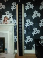
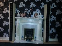
Now match that with the attached and you should have a marriage made in heaven....The group delay performance of this BMR line array is astonishing...
With no crossover, active or passive and only some Eq applied at source ( JRiver from a Lap Top) and no correction networks the 16 BMR drivers launch a totally coherent "cylinder of sound" into the room...I have been looking for an amp like yours for a few years.
LC can we talk about another commercial venture??!
Hy Byrtt,
I may have the answer to that one...!
Off Topic so happy to PM or link a spin off thread.
I am a humble speaker guy and waaaay out of my depth with amp design...
But from what I can gather you guys ( Lazy Cat being The designer) have come up with a rather unique power amp which majors on time coherent, broad frequency response, high slew rate, low distortion and drum roll....perfect group delay performance!
Now match that with the attached and you should have a marriage made in heaven....The group delay performance of this BMR line array is astonishing...
With no crossover, active or passive and only some Eq applied at source ( JRiver from a Lap Top) and no correction networks the 16 BMR drivers launch a totally coherent "cylinder of sound" into the room...I have been looking for an amp like yours for a few years.
LC can we talk about another commercial venture??!
Attachments
Well, it is more about LF distortions: Yes, the cap in the feedback path reduce the gain, as can do an input capacitance and change delay accordingly. But it adds another more important evil, on my point of view: It reduce in the same time error cancellation efficiency due to phase difference between input signal and feedback one, several octaves after the FC.First class audioband groupdelay 😀
A 10Hz FC will increase significantly the 100Hz distortion. As much as a 200KHz FC will have a significant impact on 20KHz HD.
Thanks Christophe that explanation i understand, opposit when you/sonya/Andrej roll out then i goWell, it is more about LF distortions: Yes, the cap in the feedback path reduce the gain, as can do an input capacitance and change delay accordingly. But it adds another more important evil, on my point of view: It reduce in the same time error cancellation efficiency due to phase difference between input signal and feedback one, several octaves after the FC.
A 10Hz FC will increase significantly the 100Hz distortion. As much as a 200KHz FC will have a significant impact on 20KHz HD.
, but gets impressed. Of course it was for other technical improvement, which at same do nicer groupdelay just teasing. Apropos groupdelay this is also affected in motion impedance correction microseconds by zobel, and for certain amps at resonance could run to miliseconds in my trial simulations. Have not knowledge to compose network for simulating a speaker, i just run two simulations one with load as RE and one with the resonance impedance as load and put both in same plot then see time differences. Exited to get reason/fix for Marko's VSSA probably some of your last posts about it.Hi can imagine they sound good, also very nice fireplace......But from what I can gather you guys ( Lazy Cat being The designer) have come up with a rather unique power amp which majors on time coherent, broad frequency response, high slew rate, low distortion and drum roll....perfect group delay performance!
Now match that with the attached and you should have a marriage made in heaven....The group delay performance of this BMR line array is astonishing...
With no crossover, active or passive and only some Eq applied at source ( JRiver from a Lap Top) and no correction networks the 16 BMR drivers launch a totally coherent "cylinder of sound" into the room...I have been looking for an amp like yours for a few years.....
Just for info i am hobyist not educated or pro in audio, but of course have a view.
VSSA is very speedy it is a current feedback amp, very low distortion and enorm bandwith. Because of a cap with i think three funktions the groupdelay in lows are not as one think when seeing schematic. There are no caps in signal path but this cap are amps leg to reproduce swing. See post #2383 here link http://www.diyaudio.com/forums/vend...lateral-mosfet-amplifier-239.html#post3633565 for simulation, don't zoom in to 1uS or nS with standard cap then lows are out of plot. My teaser post to ESPERADO about "First class audioband groupdelay" was because his new schematic proposal adds two more BJT devices which makes it pure DC coupled i think with linear groupdelay in lows down to DC.
For your own use i can mention author had claimed it can do 2R with right care not exeeding 8A output device limit (do a low voltage high current PSU), this i imagine would be good for 16 times speaker devices.
Myself can use years for getting one speaker device up running 😀, you done sixteen a side very 😎
Last edited:
LC can we talk about another commercial venture??!
Hi O.A.

After sending out last shipment I stil have 16 VSSA PCB sets on the stock. But these are really the last ones, so if anyone interersted ...
Best regards, L.C.

BTW very nice speakers you've made

Hello again,
second channel soldered, behaves the same as the first,
maximum output bias 3.7V (168mA).
Lazy cat, any advice?
Regards
Marko
On the top of R18 (1k) solder one 4,7 k the same size SMD resistor (both parallel) and you will get desired Iout bias. It looks like TR3 doesn't goes to zero resistance, so the parallel resistor to R18 will help to solve the problem. 😉
- Home
- Vendor's Bazaar
- VSSA Lateral MosFet Amplifier