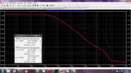
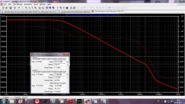
Exactly proportional to the 1kHz, means the open loop gain is yet decreasing of 6dB/oct at 1kHz ?Lateral MOSFET OPS.
even if distortion at 20 kHz is not something to write home about.
Or just an effect of those strange local comps ?
Can-you publish FFTs, please ?
Last edited:
Exactly proportional to the 1kHz, means the open loop gain is yet decreasing of 6dB/oct at 1kHz ?
Or just an effect of those strange local comps ?
Can-you publish FFTs, please ?
Not exactly 6dB/oct, a bit steeper and moved to the higher frequences.
Attachments
At last!I those last two CFA amp I am back to the current conveyor used in my GainWire pre amp, just in this case it's diamond but not with Baxandall pairs. No big difference in both cases.
Someone mentions the difference between the 2 types of evil Diamond i/ps 🙂
Anyone care to pontificate on the theoretical pros & cons?
Can we continue this on my TPC vs TMC vs Pure Cherry thread?Yes, of course. But most of the excess phase will be from the slow outputs and drivers so I would be surprised if the omission of just the comparatively fast IPS means you can safely quadruple the ULGF.
... loadsa good & important stuff ...
There's loadsa stuff Guru Zan has brought up .. some of which I have strong opinions on and some which I dunno. But he's highlighted some really important points in the recent past that have led to 'Ah Ha!' moments for me this Millenium.
Alas, my most reliable (ie closest to 'real life') examples are all VFAs so not appropriate to this thread.
However, I would still like a good way to look at the 'main loop' for CFAs so please don't stop working on this.
Doing more work, my initial thought that your 'Tian probe between OPS and the feedback take-offs' is looking at the VAS+OPS+Cherry 'inner loop' seems to be not quite true though it is a useful alternative view.
So I'm back to square one, lacking both Tian tools which I used to get the evil ULGF & margins in my #499 example on this thread. 😡
Can we continue this on my TPC vs TMC vs Pure Cherry thread?
Sure. And probably some of the stuff in Dado's 200W thread too.
You know you can click on "Multi-Quote This Message" and then "Post Reply" in a different thread? Just check that you confirm the cross thread quote.
Best wishes
David
Should qualify that as 'main loop' for 'simple CFAs' .. not the evil Diamonds 🙂However, I would still like a good way to look at the 'main loop' for CFAs so please don't stop working on this.
I have done this - very easy to do. I may post up the concept diagram in the next few days.
🙂😎
Should qualify that as 'main loop' for 'simple CFAs' .. not the evil Diamonds
"Outer" loop. "Main" loop implies it's more important😉
And it's already done, will post in the other thread.
Best wishes
David
But it IS more important 🙂"Outer" loop. "Main" loop implies it's more important 😉
I have amplifier that better distortion figure than VSSA, but VSSA sound better. If I design an amplifier, my priorities are:
1. slew rate
2. IM distortion
3. S/N ratio
4. THD
5. Damping/output impedance
I can not hear any different about sinus with 0.01% distortion and 0.001% distortion. And I choose a quality of mid and treble rather than bass.
1. slew rate
2. IM distortion
3. S/N ratio
4. THD
5. Damping/output impedance
I can not hear any different about sinus with 0.01% distortion and 0.001% distortion. And I choose a quality of mid and treble rather than bass.
Last edited:
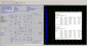
my 0.02: 2stageEF as current feedback amplifier variant 200W8R
Attached my CFA variant using 2stageEF OPS.
Gain > 30x
GM ~ 60 degree
PM ~ 10 db
THD20k@200W@8R
0.001%
THD20k@50W@8R
0.0003%
BR, Toni
Attached my CFA variant using 2stageEF OPS.
Gain > 30x
GM ~ 60 degree
PM ~ 10 db
THD20k@200W@8R
0.001%
THD20k@50W@8R
0.0003%
BR, Toni
Attachments
Attached my CFA variant using 2stageEF OPS.
Gain > 30x
GM ~ 60 degree
PM ~ 10 db
THD20k@200W@8R
0.001%
THD20k@50W@8R
0.0003%
BR, Toni
Awsome!
A beginer's question: The input transistors, Q15 and Q12, seem to be operating in quasi-saturation zone --- they have only slightly over 0.6V across C-E. Can they be somehow made work in a higher Vce? Will that make any improvement to THD and other performance? Thanks.
Attached my CFA variant using 2stageEF OPS.
...
Update:
- LF distortions are terrible high with C14/4700µF. Setting C14 to 100000µF helps a lot.
- Offset is about 30 - 40mV - for me too high. Without C14 offset would be about 200mV - inacceptable.
Update:
- LF distortions are terrible high with C14/4700µF. Setting C14 to 100000µF helps a lot.
- Offset is about 30 - 40mV - for me too high. Without C14 offset would be about 200mV - inacceptable.
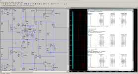
Attached an offset compensation variant. Question to our CFA gurus: is this a good idea to correct offset this way? LF Distortions maybe acceptable (10ppm) at full power.
Br, Toni
Attachments
Last edited:
1- Nothing new, the only difference with VFA is the high impedance of the feedback LTP's inputs. This makes the amp a lot sensible to the quality of the lytic, sonic side. The only alternative is a servo to keep offset stable with temp changes. A good choice with CFA, on my point of view with its low impedances. A little more complicated, but less expensive than a good big lytic, anyway.Update:
- LF distortions are terrible high with C14/4700µF. Setting C14 to 100000µF helps a lot.
- Offset is about 30 - 40mV - for me too high. Without C14 offset would be about 200mV - inacceptable.
btw: offset have to be <5mv in all circumstances. No way to adjust-it by the currents in your CCS ?
...
btw: offset have to be <5mv in all circumstances. No way to adjust-it by the currents in your CCS ?
Thx! Offset: Agree!
Have not tried to adjust by CCS current. Worth a try.
BR, Toni
Does work, but worsens THD extremely. So better to use a servo or this simple circuit.Thx! Offset: Agree!
Have not tried to adjust by CCS current. Worth a try.
BR, Toni
R6 is to linearize the bias spreader over a wider temperature range.Is-it on purpose R6 is not symmetrical ?
- Home
- Amplifiers
- Solid State
- CFA Topology Audio Amplifiers