🙂 Things are running relatively fast, we have some promising circuits, manage to get rid of the bias voltage sources, and first tests on breadboard for output offset voltage was much better than I thought at the beggining.
No need for output capacitors or DC servo.
No need for output capacitors or DC servo.
Yes, the secret is still Kirchoff's law.
The supply is still floating, but it does not swing (so much) with the output signal, only with the input.
We will NOT publish until it is fully tested and listened to, but Sergio is very fast.
We might be making PCBs for test soon.
🙂
There is a price to pay though -- 2 Idss matched pairs of 2SK170/2SJ74-BLs for each single ended output current of 4mA.
That is a lot of pairs for ES9018 in stereo, less so for 1794, etc.
Does not work with SEN. I tried.
So IMHO SEN V18 is still the solution for ESS fans.
And of course you can use LSJ74, if you want to pay 6USD for them, unmatched.
Keep watching,
Patrick
Kirchhoff
By the kirchhoff law, the current noise generated in the current source will return to the current source, not the output.
 and noise must obey the law 🙂
There is a price to pay though -- 2 Idss matched pairs of 2SK170/2SJ74-BLs for each single ended output current of 4mA.
That is a lot of pairs for ES9018 in stereo, less so for 1794, etc.
So IMHO SEN V18 is still the solution for ESS fans.
Do you always need as many pairs of of input transistors as output transistors... so if you are using 2 Idss matched pairs of 2SK170/2SJ74 as input - do you need 2 pairs as "output" also, or would one output pair be enough anyway?
If you only need one pair at the output, well then i don't see any big trouble with it, since you would only need one pair extra transistors compaired to CEN - and it would still be VERY interesting for ESS users (like myself).
Anyway - looking forward for your progress!
/Robert
> so if you are using 2 Idss matched pairs of 2SK170/2SJ74 as input - do you need 2 pairs as "output" also
If I were to do it, yes.
> since you would only need one pair extra transistors compaired to CEN ...
You have not seen the whole circuit yet.
But yes, nothing will stop you from making it possible for the 9018.
That is if you are prepared to use 16 pairs of matched K170/J74 plus 12x 2SK369Vs, plus 4x 18V floating supply as before.
(for 2 channel balanced output)
Whether it is a better solution than SEN V18 is another matter.
I cannot answer that one yet till we have built and listened.
We'll see.
Patrick
By the way - when matching for CEN circuit - then the most important part is that the individual 74/170 pairs are matched? I mean - even if the input stage do have two pairs - it doesn't matter that much (performance wise) if one of the pairs is approx 10.0mA and the other 8.5mA? it's more important to have balance between the lower and upper half?
Already have the SEN with 3x 2SK369V pairs per SEN circuit, but improvement is always fun 🙂
Already have the SEN with 3x 2SK369V pairs per SEN circuit, but improvement is always fun 🙂
In theory yes.
In practice you also want similar dissipation on all devices.
So NN (or PP) match should still be say 1mA or so.
I think it will be different, rather than better or worse.
But time will tell.
Patrick
In practice you also want similar dissipation on all devices.
So NN (or PP) match should still be say 1mA or so.
I think it will be different, rather than better or worse.
But time will tell.
Patrick
Yummy - I'm ready to invest part of my FET collection to try this beast with the 9018 🙂But yes, nothing will stop you from making it possible for the 9018.
That is if you are prepared to use 16 pairs of matched K170/J74 plus 12x 2SK369Vs, plus 4x 18V floating supply as before.
(for 2 channel balanced output)
Although absolutely happy with my SEN, I was planning to try the CEN anyway...
For those interested, here is our quick-&-dirty prototype of a SEN IV for PCM1794.
You got this working yet? I never got around to trying your simple bias solution. Curious to know whether it's stable enough to perform well.
It is stable enough. That we have tested and the results are posted.
But we have not tested it on the DAC.
The original PCB needs the analog stage stripped and replaced first.
Patrick
But we have not tested it on the DAC.
The original PCB needs the analog stage stripped and replaced first.
Patrick
Hi,
The simple JFET ccs not only works stable, but may easily be trimmed after due warm-up and is probabely the lowest noise ccs one could us here.
The ccs will be the dominant noise source of the complete circuit!
I tested several ccs structures and the JFET remained choice no1 and I use it for years in my iv circuits for the PCM179x.
Just make sure that its heavily degenerated to achieve a high enough impedance, as too low inpedance values affect THD.
JFETs like the 4391 are also a good choice here, if one doesnt want to rely on obsolete parts.
jauu
Calvin
Only the old Siliconix datasheet has a noise figure for the 4391 of 3nV/(sqrtHz).
All currently available ones (Philips, Fairchild, OnSemi) are not specified.
So 2SK369V and the like is still the better choice I think.
You can also use 2SK246BL and degenerate to 2mA or so.
Need to use 3x in parallel.
Patrick
All currently available ones (Philips, Fairchild, OnSemi) are not specified.
So 2SK369V and the like is still the better choice I think.
You can also use 2SK246BL and degenerate to 2mA or so.
Need to use 3x in parallel.
Patrick
Hi,
The interesting part about the 4391 is its high idss of ~100mA.
That allows for a a large valued source resistor, making the ccs stiffer and less noisy. Paralleling devices to achieve suffuciently large dc-currents reduces Zout and increases noise again.
So I still think, that a single high Idss JFET is a prefferable choice.
jauu
Valvin
Isn't it that random noise reduce by sqrt of n, where n is the number of devices in parallel ?
Else why should they bother in phono preamps ?
Patrick
Else why should they bother in phono preamps ?
Patrick
Hi,
The simple JFET ccs not only works stable, but may easily be trimmed after due warm-up and is probabely the lowest noise ccs one could us here.
The ccs will be the dominant noise source of the complete circuit!
I tested several ccs structures and the JFET remained choice no1 and I use it for years in my iv circuits for the PCM179x.
Just make sure that its heavily degenerated to achieve a high enough impedance, as too low inpedance values affect THD.
JFETs like the 4391 are also a good choice here, if one doesnt want to rely on obsolete parts.
jauu
Calvin
Hi Calvin 🙂
I also think that the 4391 is a good option. As the 2SK369V is.
But you have to take a better look to the topology, please.
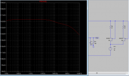
I have developed this concept of floating current source exactly to eliminate the noise from the current sources in a folded cascode. As the current source is floating, any current noise that is produced in the current source will have to return to the current source.
The impact of the current source noise in this topology is close to none.
Also the output impedance of the ccs is not a problem, the circuit works with low distortion even with a resistor as current source
The PSRR of this topology is also very high.
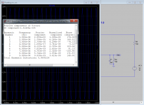
In the first image is the PSRR of one of the circuits we have, the other image is the distortion with a 150 ohms resistor as current source .
(simulating a pcm1794 at 7,8ma p-p).
sorry for not show all the circuit, but is under development.
Attachments
Last edited:
for public use or proprietary?sorry for not show all the circuit, but is under development.
Interested to learn how to sim a I/V converter!! So more for me too learn in ltspice.
- Home
- Source & Line
- Digital Line Level
- Zen -> Cen -> Sen, evolution of a minimalistic IV Converter