build your self a light bulb device that limits current to amp,lots of threads with that discussion line in it ....simple really just an incandescent bulb 40-60 watts in line with hot conductor keeps stuff from going poof...
Regards, Elwood
Regards, Elwood
To rule out the trimpots, which I've found the hard way tend to go first in situations like this measure resistance across the parallell resistor of P/1P2. if resistance with P2/p1 changes with adjustment then he pots are working. You want to measure R3 and R4. Amp should be off while doing this.
I had a P2 pot go when a mosfet thermistor grounded essentially sending DC to ground, kinda like what was going on with your grounded diode situation.
Other than that, check the Jfets and mosfets. Both of which will require desoldering/isolating. I'd check the pots first.
You cant see anything burned (resistors), right? Check the bias resistors to make sure they are not open. How much DC volatage on output? A few hundred mv or like 24V?
I almost wish there was something burned so I would have evidence .
There is less than a volt on the outputs.
I'll do some testing tomorrow starting with the trim pots.
I'm getting pretty good at desoldering 🙂
There is less than a volt on the outputs.
I'll do some testing tomorrow starting with the trim pots.
I'm getting pretty good at desoldering 🙂
I tested P1 and P2 they are fine.
So I pulled out Q5 and Q6 and they tested fine using this procedure:
Test a transistor with a multimeter | Vetco Electronics
What should I pull out next Q1/Q2 or Q3/Q4
So I pulled out Q5 and Q6 and they tested fine using this procedure:
Test a transistor with a multimeter | Vetco Electronics
What should I pull out next Q1/Q2 or Q3/Q4
I almost wish there was something burned so I would have evidence .
There is less than a volt on the outputs.
I'll do some testing tomorrow starting with the trim pots.
I'm getting pretty good at desoldering 🙂
I HATE desoldering! What's your technique? I usually end up lifting a trace from overheating.
Are you sure you are turning the pots the proper direction?
What is the most bias you can get with zero offset?
What is the most bias you can get with zero offset?
I HATE desoldering! What's your technique? I usually end up lifting a trace from overheating.
Um, I don't know if my technique is that great. I cheated on the ztx 450/550. I just cut the pins leaving them long enough to test. Then I just desolder the stubs left in the board. This technique could get expensive on the J74/K170.
I do the same thing with wires. I cut the wire leaving a little stub. Next I hit it with the soldering iron and pull the stub out with a needle nose. I put a little bit of solder on the tip so it melts whatever I'm desoldering fast. Then hit the via again with the iron and solder sucker. I use quite a bit of heat 600° really fast.
Are you sure you are turning the pots the proper direction?
What is the most bias you can get with zero offset?
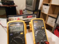
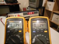
I can get .13V bias with 0V offset.
This reading is with 27 turns on P2 and 7 turns on P1
I can get .59V bias with .23 offset.
This reading is with 30 turns (maximum) on P2 and 10 turns on P1
The mosfets don't even get warm in either one of these scenarios.
Should the bias on the two sides go up independently? because they don't. If I turn P2 way up then turn P1 a little the bias on both sides starts to go up.
Attachments
Hi Kevin,
So you mean you can go to the biasing procedure without evidence of any smoke? This should be a good sign.
Bring P1 and P2 to 0 again as starting point.
Then turn slightly P1 and P2 equally until you can get a small amount of bias reading on both N and P channel.
Then turn one pot either P1 and P2 until you can balance the DC output offset. Yes turning either P1 or P2
will adjust both N and P channel bias reading. Set very low bias first...let say 0.1V first. Then cover the amp for a little
while lets say 30min...then you check the behavior for both N and P channel...then repeat the procedure lets say go
at 0.2V then cover the amp for another 30min...then repeat the procedure until you get the desired bias.
If running out of turns and still cannot get the desire bias, you need to increase the value of the parallel resistors.
Last edited:
Hi Kevin,
It sounds like you may have a parallel resistor that may be wrong the guys are right set bias on both side alittle at a time.
Regards, E
It sounds like you may have a parallel resistor that may be wrong the guys are right set bias on both side alittle at a time.
Regards, E
Make the resistors on parallel with the pots bigger- more ohms. Try 4.7k or so. Or just add a resistor in series if you don't have the right value on hand. It sounds like things are reacting normally.
I don't understand why the Q3 and Q4 don't even get warm. On other another amp I built (Zen 1) the mosfets got hot right away.
.13 is about 6 watts. On a big heatsinks they won't warm up very much. Change those series resistors, and things will probably work as expected.

Thank You Everyone
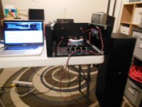
Thanks for all your help! I'm listening to music on the F5 as I type (well one channel anyway). I thought I had some ZTX 450/550 but I don't. So I can't put the other channel back together until DigiKey ships me my parts.
Thanks to everyone who post to F5 threads, you may not know you helped but you did. Thank You Nelson Pass!
Attachments
😎
If you havent ordered them already I think I have some of the ztx devices I could throw in an envelope and send you. That way you wont have to pay the shipping charges for parts that cost a few cents. Let me know.
Thanks for all your help! I'm listening to music on the F5 as I type (well one channel anyway). I thought I had some ZTX 450/550 but I don't. So I can't put the other channel back together until DigiKey ships me my parts.
Thanks to everyone who post to F5 threads, you may not know you helped but you did. Thank You Nelson Pass!
If you havent ordered them already I think I have some of the ztx devices I could throw in an envelope and send you. That way you wont have to pay the shipping charges for parts that cost a few cents. Let me know.
😎
If you havent ordered them already I think I have some of the ztx devices I could throw in an envelope and send you. That way you wont have to pay the shipping charges for parts that cost a few cents. Let me know.
Thanks for the offer. I ordered some other parts anyway. Got to get going on an Aleph J you know😉
- Status
- Not open for further replies.
- Home
- Amplifiers
- Pass Labs
- F5 Build: Problems on first start-up