I went to start up my recently finished F5 and didn't have good results. I had tested the power supply before hooking up the amplifier boards and it worked fine +25/-25 volts. I was following the start-up procedure from the F5 Build Guide so all trim pots where turned fully counter-clockwise. I'm using a variac and three multi-meters. I started to turn up the voltage and all meters stayed at 0 volts. But when I got to about 50% on the variac (120v mains voltage) the thermistor going to ground began to smoked and the fuse blew. I've checked everything I can think so far. Thanks in advance for your help.
I went to start up my recently finished F5 and didn't have good results. I had tested the power supply before hooking up the amplifier boards and it worked fine +25/-25 volts. I was following the start-up procedure from the F5 Build Guide so all trim pots where turned fully counter-clockwise. I'm using a variac and three multi-meters. I started to turn up the voltage and all meters stayed at 0 volts. But when I got to about 50% on the variac (120v mains voltage) the thermistor going to ground began to smoked and the fuse blew. I've checked everything I can think so far. Thanks in advance for your help.
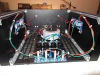
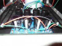
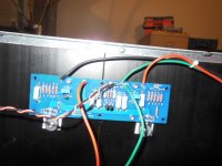
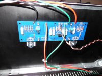
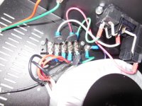
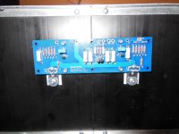
Clear nice pics showing wiring please.
")
Russellc
Did you confirm that the trim pots were at maximal resistance before powering up with the variac? Depending on which pots and which boards, maximal could be completely clockwise or completely counterclockwise. I (and many others) have experienced what you have encountered by having pots maximally turned the wrong direction on startup.
Did you confirm that the trim pots were at maximal resistance before powering up with the variac? Depending on which pots and which boards, maximal could be completely clockwise or completely counterclockwise. I (and many others) have experienced what you have encountered by having pots maximally turned the wrong direction on startup.
Pardon me, I have been very confuse what is maximal resistance nor
either which is clockwise or counterclockwise turn of the pot.
Im just measuring the parallel resistor to be 0ohm before firing up first time.
Regards.
I was completely backwards in what I wrote.
AudioSan, looking at the schematic for the F5, having P1 to the minimum (let's say 0 ohms) allows maximal positive voltage to the gate of Q3 (through gate-stopper, R47), which will make Vgs on Q3 approach zero or some minimal value, with resultant minimal drain current through Q3.
And then, as the resistance of P1 is increased, the gate of Q3 becomes more negative with respect to the source, and Q3 Id begins to take off.
Did I finally get it right or am I still confused in my thinking?
Thanks!
Hi Kevin,
Just based on my experience, when you are turning up the variac and at 50%,
do you still have 0 DC Offset on the output terminal?
If yes, you should have set the trim pot correctly at least on the channel you are testing.
How about the other channel?
Do you connect both channel same time?
Would recommend to fire-up 1 channel at a time and if you are sure both channel are working that's
the time you should join it together.
First thing first, take a good rest and comeback later to check your amp.
Can you draw your primary on how you exactly do this?
What is the violet wire color on the chassis ground BTW?
Regards,
Did you confirm that the trim pots were at maximal resistance before powering up with the variac? Depending on which pots and which boards, maximal could be completely clockwise or completely counterclockwise. I (and many others) have experienced what you have encountered by having pots maximally turned the wrong direction on startup.
I find that when using variac, where the pots are set really isnt that critical. As the voltage is turned up, eventually bias starts to show. Just keep it in check with gradual turning up of the voltage, and adjustment of bias. I adjusted pots to middle range to start.
Russellc
I verified that the trim pots were originally set in the correct position. I turned the pots completely the other way (clockwise) and turned up the variac a little bit. I started to get a little voltage across R11 and R12.
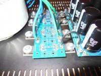
I have leds on the power supply board and I did notice when powering down one stayed lit and the other one went out.
I'll try hooking up just one channel at a time.
Thanks again for your help.
I have leds on the power supply board and I did notice when powering down one stayed lit and the other one went out.
I'll try hooking up just one channel at a time.
Thanks again for your help.
Kevin:
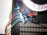
First clue is one of the LED's didn't light up. I'd disconnect the boards and troubleshoot the PSU first. Wiring looks good in the pics, but we can't see the rectifiers. Double check the Transformer wiring. Maybe hit all the solder joints on the PSU board and rectifiers again while you are at it and check for bridged joints, etc.
While the boards are disconnected from the psu check to make sure the mosfets aren't grounded. Also, check to make sure the tip of the mosfet thermistors aren't conductive. Sometimes they are and once they touch those washers on he mosfets they go boom. I know this from experience.
Before you do anything measure between the + and minus speaker posts (WITH THE AMP OFF!). You should have some resistance, like a few hundred ohms. If you don't or if if it's open then you have got issues with a speaker post/rca touching the chassis, or a grounded mosfet.
All of this may or may not lead to your ground thermistor issue, I don't know. But i am just reciting the issues I dealt with when starting my F5.
I tore the whole amplifier apart and found something weird. When I pulled the rectifier board a couple of the thermal pads under the diodes had perforations in the shape of a circle.
Originally when drilling the holes for the diodes I started in the wrong spot. These extra holes ended up directly under the body of some diodes. I didn't realize these holes had burs on them. The burs must have penetrated the thermal pad and so the back of the diodes where conducting to the chassis.
I did test the power supply like I had said, but when I did the wire going to ground with the thermistor wasn't hooked up.
Clear as mud?
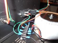
I did make some changes when putting the amp back together:
I switched to a six position barrier strip and slid everything over. Now the grounds wire doesn't snake under the wires from the primary.
I ground down one side of the washers so they are not in contact with the thermistors.
I just tested the power supply and it works as it should.
Tomorrow I'll hook up one channel at a time and see if the amp boards work.
Thanks again for your help!
Originally when drilling the holes for the diodes I started in the wrong spot. These extra holes ended up directly under the body of some diodes. I didn't realize these holes had burs on them. The burs must have penetrated the thermal pad and so the back of the diodes where conducting to the chassis.
I did test the power supply like I had said, but when I did the wire going to ground with the thermistor wasn't hooked up.
Clear as mud?
I did make some changes when putting the amp back together:
I switched to a six position barrier strip and slid everything over. Now the grounds wire doesn't snake under the wires from the primary.
I ground down one side of the washers so they are not in contact with the thermistors.
I just tested the power supply and it works as it should.
Tomorrow I'll hook up one channel at a time and see if the amp boards work.
Thanks again for your help!
Attachments
I'm stumped again. I have the power supply issues worked out. I hooked up one amplifier board and started to turn up P1 and P2 but I get essentially no voltage on R11 and R12 but I do get some voltage on the output. I checked the pinouts on the transistors over and over. Getting frustrated, better quit for tonight.
- Status
- This old topic is closed. If you want to reopen this topic, contact a moderator using the "Report Post" button.
- Home
- Amplifiers
- Pass Labs
- F5 Build: Problems on first start-up